
Method for reducing concentration of agglomerate fog

A fog concentration and aerosol technology, applied in separation methods, chemical instruments and methods, dispersed particle separation, etc., can solve the problem of no means of controlling fog, and achieve the effects of improving visibility, low energy consumption, and long transmission distance.

Inactive Publication Date: 2022-01-07
星诺大气环境科技(天津)有限公司 +1
View PDF5 Cites 0 Cited by
  • Summary
  • Abstract
  • Description
  • Claims
  • Application Information

AI Technical Summary

Problems solved by technology

There is currently no means of controlling cloud fog

Method used


Image

  • Method for reducing concentration of agglomerate fog
  • Method for reducing concentration of agglomerate fog
  • Method for reducing concentration of agglomerate fog

Examples


Embodiment Construction

[0030] The technical solution of the present invention will be described in detail below in conjunction with the accompanying drawings.

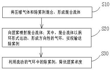
[0031] like figure 1 As shown, a method for reducing the concentration of fog in the embodiment of the present invention comprises the following steps:

[0032] In step S10, the compressed gas and the demister are mixed to form a mixed fluid.

[0033] In step S10, an air compressor may be used to provide compressed gas. The compressed gas may be compressed air. Preferably, an air compressor is used to provide compressed gas. Compressed air can also be provided by an air piston machine. Compressed gas pulse flow to input compressed gas. The compressed gas in the mixed fluid is mixed with the demister, and the formed air mass contains the demister. The demister flows with the air mass.

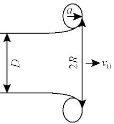
[0034] like figure 2 As shown, the vortex ring is a state of vortex motion. D is the outlet diameter of the vortex ring tube. For example, the pist...


PUM

PropertyMeasurementUnit
diameteraaaaaaaaaa

Abstract

The invention discloses a method for reducing the concentration of agglomerate fog, and the method can effectively reduce the concentration of agglomerate fog. The method comprises the following steps: S10, mixing compressed gas and a defogging agent to form a mixed fluid; S20, spraying the mixed fluid to the agglomerate fog, wherein the mixed fluid moves in a vortex ring form to form a directional gas ring so as to convey the defogging agent; and S30, reducing the concentration of agglomerate fog and improving the visibility by using the demisting agent in the flowing gas ring.

Description

technical field [0001] The invention relates to a method for reducing cloud fog concentration. Background technique [0002] At present, the method of long-distance transportation of air mass is realized by a high-power jet fan. One of the uses is to spray water mist into the airflow to achieve air dust reduction. At present, the main disadvantages of long-distance air mass transmission are high power and limited transmission distance. [0003] At present, the fog control technology is mainly based on monitoring and alarming. By installing relevant detection systems at certain distances in areas prone to fog, the visibility sensor or video analysis technology is used to monitor the fog in real time. At present, there is no means of controlling cloud fog. When a cloud of fog occurs, the system will detect the concentration of the cloud in real time, give an early warning, and carry out early warning or management of transportation and work that requires visibility. The gr...

Claims


Application Information

Patent Timeline
Patent Type & Authority Applications(China)
IPC IPC(8): B01D47/06
CPCB01D47/06
Inventor 黄庆周爱军韩旭
Owner 星诺大气环境科技(天津)有限公司
Learn More