Ratchet type cable shears with adjustable shearing range
An adjustable and ratchet-type technology, which is applied in the direction of cutting/split cable equipment, cable installation, cable installation device, etc., can solve the problems of small cutting range, inconvenient use of handle telescopic, etc., to expand the working range and facilitate Cutting work, the effect of improving convenience
- Summary
- Abstract
- Description
- Claims
- Application Information
AI Technical Summary
Problems solved by technology
Method used
Image

Examples
Embodiment 1
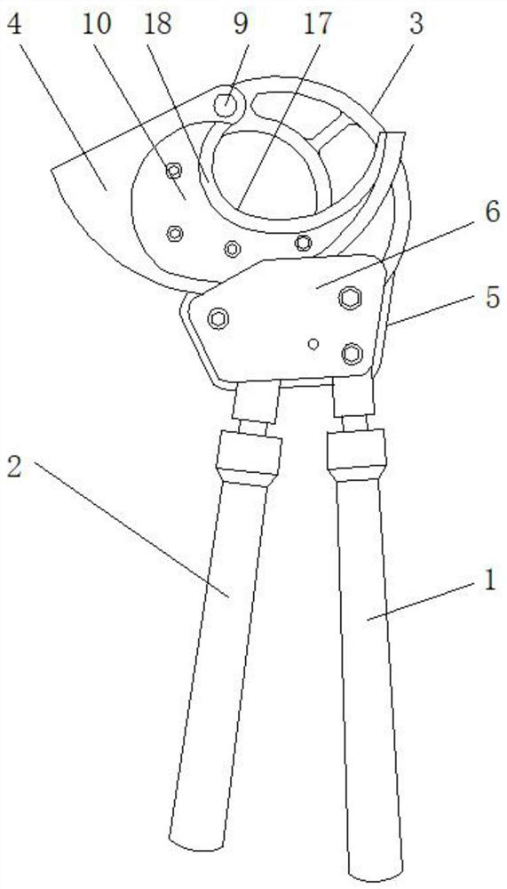
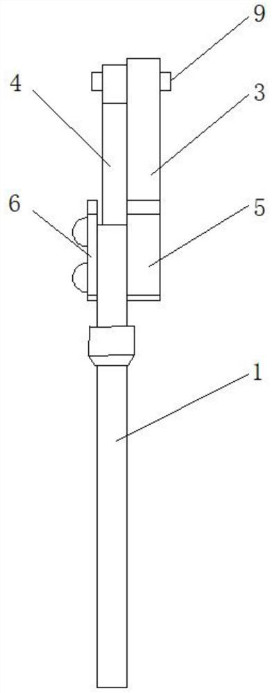
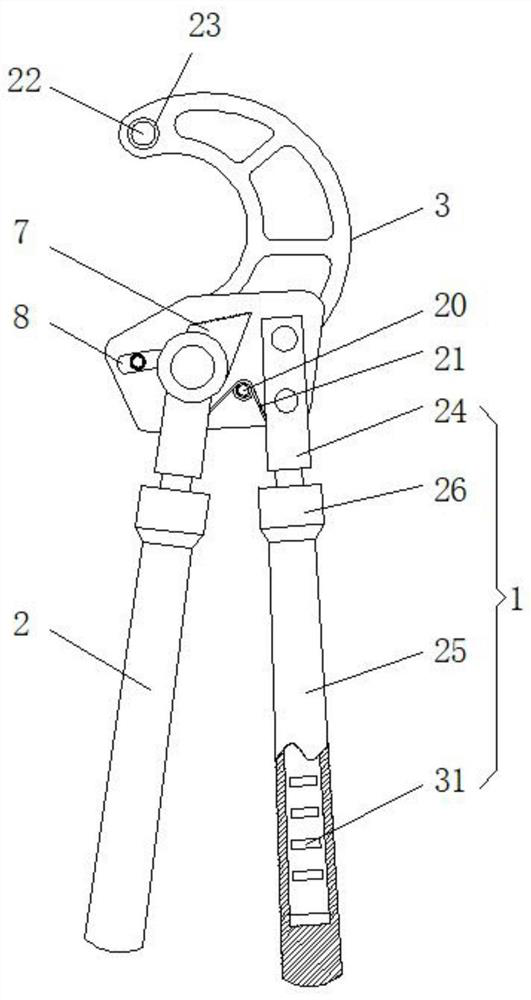
[0026] Example 1, see Figure 1-6 , the present invention provides a technical solution: a ratchet type cable cutter with adjustable cutting range, including a fixed handle 1, a movable handle 2, a fixed knife holder 3, a movable knife holder 4, a bottom plate 5, a cover plate 6, and a rack 7 and pawl 8, the fixed handle 1 is fixedly connected to the surface of the base plate 5, the movable handle 2 is connected to the base plate 5 in rotation, and the rotating part of the movable handle 2 is provided with a rack 7 that rotates in one direction. The left side of the rack 7 is provided with a movably connected pawl 8, the surface of the base plate 5 is fixedly connected with a cover plate 6, and the end of the base plate 5 is fixedly connected with a fixed knife rest 3, and the fixed knife rest 3 The end is provided with a movable knife rest 4 that is rotatably connected, and the connection between the fixed knife rest 3 and the movable knife rest 4 is provided with a rotating ...
Embodiment 2
[0027] Example 2, see Figure 4-5 , the technical solution of this embodiment is a movable knife rest installed on a fixed knife rest. Frame 4 is made up of base plate 12, locating groove 13 and locating pin 14, and the surface of described base plate 12 is provided with locating groove 13, and the surface of described locating groove 13 is fixedly connected with the locating pin 14 of dislocation distribution, and the locating pin 14 of described locating pin The end is provided with a threaded hole 15, and the structural stability of the connection between the blade 10 and the substrate 12 is improved by providing a misaligned positioning pin 14 on the surface of the substrate 12. By providing a threaded hole 15 at the end of the positioning pin 14 , it is convenient to use bolts to fixedly connect the blade 10 to the bottom plate 5 .
[0028] The present invention is provided with the blade 10 of detachable connection on the surface of movable knife rest 4, conveniently re...
Embodiment 3
[0029] Example 3, see figure 1 and 5 , the technical solution of the present embodiment is the blade installed on the movable knife rest, in order to facilitate the disassembly and assembly of the blade and the cutting of the cable, the detachably connected blade is installed on the surface of the movable knife rest, the surface of the blade 10 Be provided with positioning hole 16, described positioning hole 16 and positioning pin 14 one-to-one correspondence, the inboard of described blade 10 is provided with shearing knife edge 17, and the edge place of described shearing knife edge 17 is provided with pushing slope 18, and described The outer side of the blade 10 is provided with a positioning bar 19, and the positioning holes 16 corresponding to the positioning pins 14 are provided on the surface of the blade 10 to facilitate the fixed installation of the blade 10 and the base plate 12, and improve the stability of the blade 10 when cutting. The cutting edge 17 edge of th...
PUM
 Abstract
Description
Claims
Application Information
 - R&D
- Intellectual Property
- Life Sciences
- Materials
- Tech Scout
- Unparalleled Data Quality
- Higher Quality Content
- 60% Fewer Hallucinations
Browse by: Latest US Patents, China's latest patents, Technical Efficacy Thesaurus, Application Domain, Technology Topic, Popular Technical Reports.
© 2025 PatSnap. All rights reserved.Legal|Privacy policy|Modern Slavery Act Transparency Statement|Sitemap|About US| Contact US: help@patsnap.com