Capacitor element monitoring method, device and system
A capacitive component and monitoring system technology, applied in the direction of capacitor testing, etc., can solve problems such as high algorithm requirements, difficult capacitor bank faults, failure to timely and accurately find faulty capacitor units, etc., to achieve strong anti-interference ability, guarantee reliability, and online Monitor Efficient Effects
- Summary
- Abstract
- Description
- Claims
- Application Information
AI Technical Summary
Problems solved by technology
Method used
Image
Examples
Embodiment 1
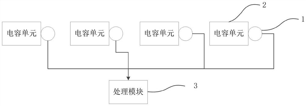
[0039] figure 1 It is a structural schematic diagram of the connection between the capacitive element monitoring equipment and the capacitive unit used in the capacitive element monitoring method provided by Embodiment 1 of the present invention; figure 2 It is a flow chart of a capacitive element monitoring method provided by Embodiment 1 of the present invention. This embodiment can be applied to the monitoring of power frame type capacitor banks, and can also be applied to the on-line monitoring of a single capacitive unit. This method can be monitored by capacitive elements equipment to perform, such as figure 1 As shown, the capacitive element monitoring device includes a shock wave detection element and a processing module, and the shock wave detection element is used to be installed on the capacitance unit to detect the shock wave information generated by the capacitance unit; the processing module and the shock wave detection Components are electrically connected; su...
Embodiment 2
[0056] Figure 5 It is a flow chart of a capacitive element monitoring method provided by Embodiment 2 of the present invention, which is optimized on the basis of Embodiment 1 above. Optionally, after determining that the capacitor unit is suspected to be faulty, it includes: sending an early warning message to a mobile terminal of an operation and maintenance personnel.
[0057] Such as Figure 5 As shown, the method includes:
[0058] S210. Acquire shock wave information of the capacitor unit detected by the shock wave detection element.
[0059] S220. Determine the number of occurrences of shock waves based on the shock wave information.
[0060] S230. Determine whether the number of occurrences of shock waves is greater than a preset number of failures.
[0061] If yes, execute steps S240 and S250.
[0062] S240. Determine that the capacitor unit is suspected to be faulty.
[0063] S250. Send the warning information to the mobile terminal of the operation and mainte...
Embodiment 3
[0067] Figure 6 It is a flow chart of a capacitive element monitoring method provided by Embodiment 3 of the present invention, which is optimized on the basis of Embodiment 1 above. Optionally, the number of the shock wave detection elements is multiple, and the multiple shock wave detection elements are respectively used for one-to-one installation on a plurality of capacitor units; the method further includes: obtaining a plurality of the shock wave detection elements Number information of the shock wave detection element obtained by numbering; correspondingly, determining the fault condition of the capacitor unit based on the shock wave information includes: determining the difference between a plurality of the capacitor units based on the shock wave information and the number information of the shock wave detection element Fault conditions.
[0068] Such as Figure 6 As shown, the method includes:
[0069] S310. Acquire shock wave information of the capacitor unit det...
PUM
 Abstract
Description
Claims
Application Information
 - R&D Engineer
- R&D Manager
- IP Professional
- Industry Leading Data Capabilities
- Powerful AI technology
- Patent DNA Extraction
Browse by: Latest US Patents, China's latest patents, Technical Efficacy Thesaurus, Application Domain, Technology Topic, Popular Technical Reports.
© 2024 PatSnap. All rights reserved.Legal|Privacy policy|Modern Slavery Act Transparency Statement|Sitemap|About US| Contact US: help@patsnap.com


