
Silencer, compressor and air conditioner

A muffler and compressor technology, applied in the field of compressors, can solve the problems of high compressor oil discharge rate, low compressor oil pool oil level, insufficient lubrication of pump body components, etc., to ensure lubrication and oil discharge rate Effect

Inactive Publication Date: 2022-01-04
GREE ELECTRIC APPLIANCES INC
View PDF7 Cites 0 Cited by
  • Summary
  • Abstract
  • Description
  • Claims
  • Application Information

AI Technical Summary

Problems solved by technology

However, due to the winding gap in the stator of the concentrated winding motor, the compressor has the following problems: the high-pressure gas compressed by the pump body assembly is discharged through the muffler, and then flows through the rotor flow hole to the upper cavity of the casing and then discharged out of the compressor
On the one hand, it leads to the high oil discharge rate of the compressor, which reduces the energy efficiency of the compressor; on the other hand, the oil level in the oil pool of the compressor is too low, and the pump oil is insufficient, which makes the lubrication of the pump body components insufficient, resulting in the reliability of the compressor. sex decline

Method used


Image

  • Silencer, compressor and air conditioner
  • Silencer, compressor and air conditioner
  • Silencer, compressor and air conditioner

Examples


Embodiment 1

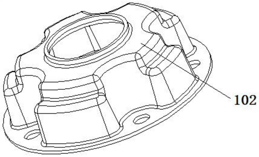
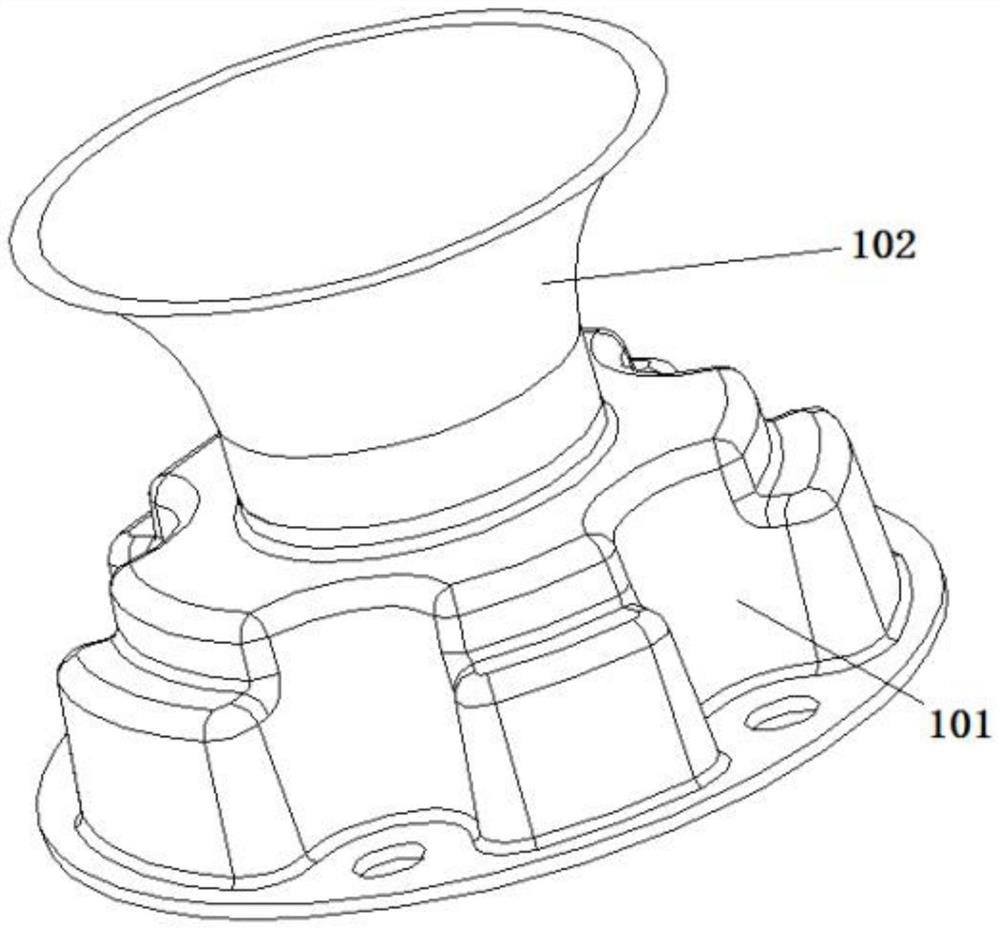
[0038] This embodiment provides a muffler, such as image 3 As shown, for a compressor, the muffler includes a sound absorbing assembly 101 and an oil retaining assembly 102, the oil retaining assembly 102 is arranged on the sound absorbing assembly 101, and the oil retaining assembly 102 divides the lower chamber of the compressor into a first chamber and a second chamber. cavity;

[0039] Specifically, after the above-mentioned structure is adopted, the refrigerating oil enters the first cavity, and under the action of the high-pressure gas discharged from the noise reduction assembly 101, enters the upper cavity of the compressor through the rotor flow hole of the compressor, and is sequentially It enters the second cavity through the stator winding gap of the compressor; at this time, due to the setting of the oil retaining assembly 102, most of the high-pressure gas is located in the first cavity, and the refrigerated oil in the second cavity will not be affected by the h...

Embodiment 2

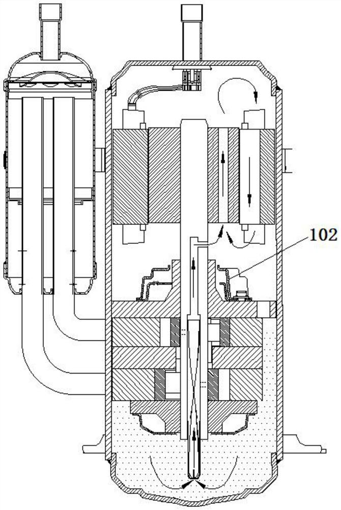
[0062] This embodiment provides a compressor, as shown in Figure 7 and Figure 8 As shown, the compressor includes the muffler 100, the pump body 200, the concentrated winding motor 300, the crankshaft 400 and the housing 500 in Embodiment 1, and the muffler 100, the pump body 200, the concentrated winding motor 300 and the crankshaft 400 are all located in the casing 500; the lower cavity 600 is formed between the pump body 200 and the concentrated coil motor 300, the muffler 100 is located in the lower cavity 600, and the upper cavity 700 is formed between the concentrated coil motor 300 and the housing 500; the crankshaft 400 is provided with an oil guide 401, the outlet of the oil guide member 401 communicates with the pump body 200 and the lower cavity 600;

[0063] The concentrated winding motor 300 includes a stator 301 and a rotor 302 that are arranged in cooperation. The rotor 302 is provided with a rotor flow hole 3021 , and a stator winding gap 3011 is formed betwee...

Embodiment 3

[0073] This embodiment provides an air conditioner, and the air conditioner includes the compressor of Embodiment 2.


PUM


Abstract

The invention discloses a silencer, a compressor and an air conditioner. The silencer comprises a silencing assembly and an oil baffle assembly, the oil baffle assembly is arranged on the silencing assembly, and the oil baffle assembly divides a lower cavity of the compressor into a first cavity and a second cavity. When the compressor operates, refrigerant oil is pumped out by a compressor oil guide part and enters the first cavity, under the action of high-pressure gas exhausted by the silencing assembly, the refrigerant oil in the first cavity can enter the upper cavity along with the high-pressure gas through a rotor circulation hole, due to the effect of gravity, the refrigerant oil in the upper cavity flows into the second cavity from a stator winding gap, and at the moment, most of the high-pressure gas is located in the first cavity under the action of the oil baffle assembly so that the refrigerant oil in the second cavity cannot be influenced by the high-pressure gas and flows into an oil pool of the compressor under the action of gravity; and therefore, the problem that a large amount of refrigerant oil is gathered between the upper cavity and the lower cavity can be solved, and lubrication and the oil spitting rate of the compressor are guaranteed.

Description

technical field [0001] The invention relates to the technical field of compressors, in particular to a muffler, a compressor and an air conditioner. Background technique [0002] With the upgrading of air-conditioning energy efficiency systems, concentrated coil motors are more and more widely used in rolling rotor refrigeration compressors due to their high energy efficiency. However, due to the winding gap in the stator of the concentrated winding motor, the compressor has the following problems: the high-pressure gas compressed by the pump body assembly is discharged through the muffler, and then passes through the rotor flow hole to the upper cavity of the casing and then is discharged from the compressor. However, the refrigerated oil in the compressor will also follow the high-pressure gas to the upper chamber of the housing, and then flow back to the lower chamber of the housing through the gap of the stator wire package. . Therefore, a large amount of refrigerating...

Claims


Application Information

Patent Timeline
Patent Type & Authority Applications(China)
IPC IPC(8): F04C29/02F04C29/06
CPCF04C29/06F04C29/068F04C29/028
Inventor 何庆南苗旺阙沛祯马舒院
Owner GREE ELECTRIC APPLIANCES INC
Learn More