Compensator for rotary working device of excavator

A technology of slewing compensation and working devices, which is applied to earth movers/excavators, construction, etc., to achieve low production costs, ensure coordination, adjust flexibility and adaptability

Active Publication Date: 2022-01-04
JIANGSU ADVANCED CONSTR MASCH INNOVATION CENT LTD
View PDF4 Cites 0 Cited by
  • Summary
  • Abstract
  • Description
  • Claims
  • Application Information

AI Technical Summary

Problems solved by technology

[0012] The purpose of the present invention is to overcome the deficiencies in the prior art and provide a compensator for excavator slewing working device, which solves the combined action flow of loading operation slewing + boom lifting in the excavator operation cycle through the mechanical structure of hydraulic valve parts For the distribution problem, the hydraulic system controls the flow through the rotary spool by introducing load pressure to control the pressure difference between the two ends of the spool without adding the pilot electro-hydraulic proportional pressure reducing valve and pressure sensor, so as to ensure the coordination of compound actions. Improve the working efficiency of the excavator; on the control side of the compensator, there is a throttle port connected to the cavity on both sides of the compensator. When the rotary compensator moves to the closed position, the flow still flows to the rotary when the rotary valve core changes direction. motor

Method used


Image

  • Compensator for rotary working device of excavator
  • Compensator for rotary working device of excavator
  • Compensator for rotary working device of excavator

Examples


Embodiment Construction

[0035] The present invention will be further described below in conjunction with the accompanying drawings. The following examples are only used to illustrate the technical solution of the present invention more clearly, but not to limit the protection scope of the present invention.

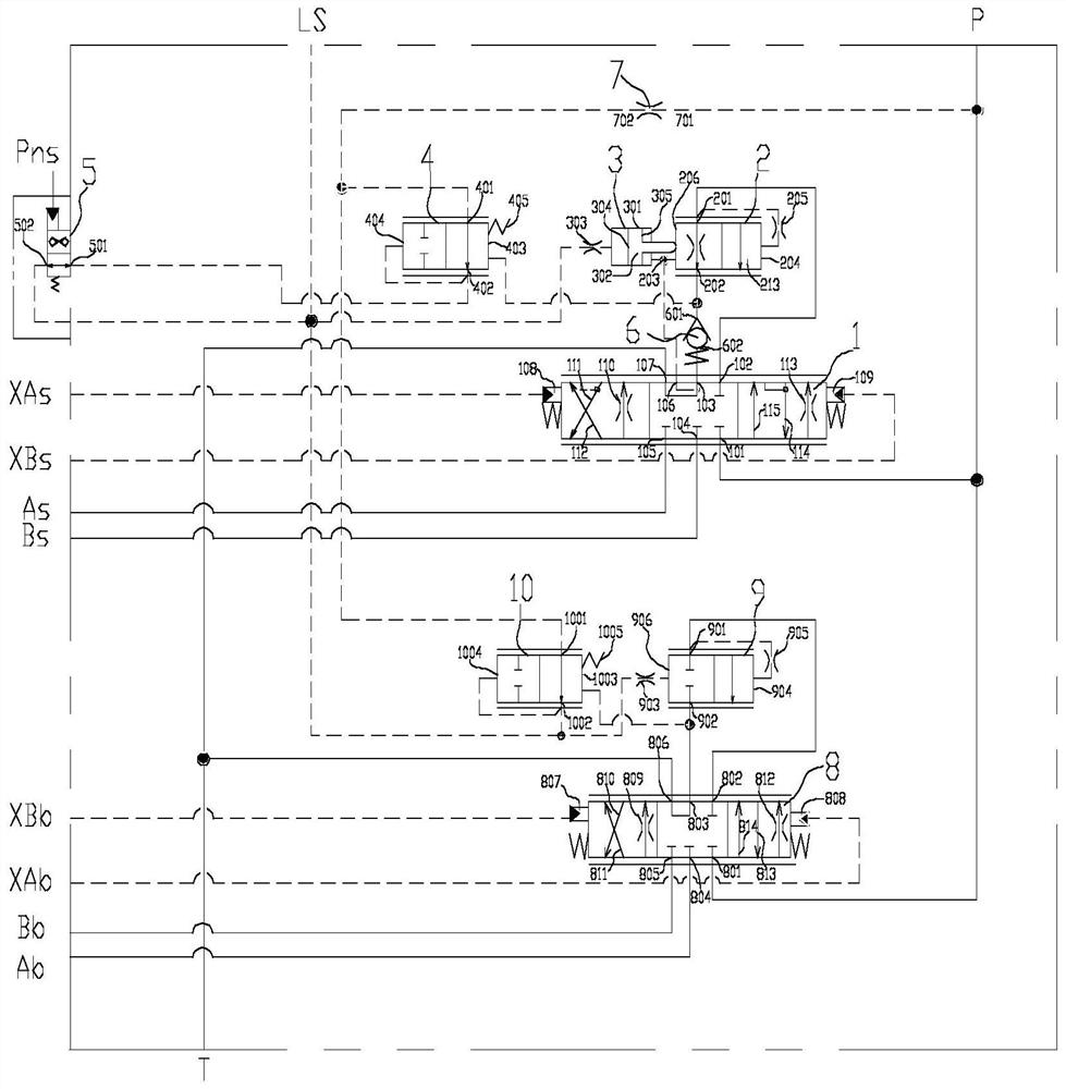
[0036] figure 1 Shown is a schematic diagram of the application of the compensator for the rotary working device in the present invention to the load-sensing multi-way valve. The schematic diagram includes: rotary reversing throttle valve 1, rotary compensator assembly 2, rotary compensator plunger assembly 3, rotary signal pressure reducing valve 4, on-off valve 5, check valve 6, orifice 7, boom The reversing throttle valve 8, the boom compensator spool 9, the boom signal pressure reducing valve 10, and the oil passages communicating with the above-mentioned various components. The oil circuit connection mode of the compensator hydraulic system for the rotary working device is as follows: the...


PUM


Abstract

The invention discloses a compensator for a rotary working device of an excavator. The compensator solves the problems of coordination of loading operation rotation and movable arm lifting composite actions and priority distribution of rotation linkage flow in the operation cycle of the excavator. When a rotary table rotates to the loading position, the lifting of a movable arm can ensure that the materials in an excavator bucket reach the safe loading height and are not collided. The designed compensator comprises a plunger assembly and a sliding valve element assembly, and the pressure behind a throttling opening of a rotary valve element of a working unit, the load pressure of a rotary motor and the signal pressure are introduced into three pressure containing cavities of the compensator through an oil way of a valve body of the working unit. The requirement for left-side and right-side rotation of the excavator can be met through one compensator at the same time. The control edge of the compensator is provided with the throttling opening communicated with the containing cavities on the two sides of the compensator, after the rotation linkage compensator moves to the closing position, when a rotation linkage valve element reverses, flow still flows to a rotary motor, and the coordination of flow distribution is achieved under the heavy load condition of a working device.

Description

technical field [0001] The invention belongs to the technical field of construction machinery, and in particular relates to a compensator for a rotary working device of an excavator. Background technique [0002] The combined action time of hydraulic excavator slewing and boom lifting occupies about 20% to 25% of the cycle time of excavator loading operation, and its operation coordination has a significant impact on the working efficiency of the whole machine. During the loading operation of the excavator, the coordination problem will lead to the risk of collision between the bucket and the truck when the turret turns to the loading position but the boom fails to lift to the unloading height. Quickly cause driver fatigue and reduce work efficiency. In addition, when the load of excavator working devices such as boom and arm is heavy and the flow needs to flow preferentially to the slewing, the traditional load-sensing multi-way valve can not meet the operation requirement...

Claims


Application Information

Patent Timeline
IPC IPC(8): E02F9/22
CPCE02F9/2264E02F9/2267
Inventor 杨涛刘美英聂文磊刘方帅
Owner JIANGSU ADVANCED CONSTR MASCH INNOVATION CENT LTD
Why Eureka
Try Eureka