
Installing method of elastic coupling

A technology of elastic coupling and installation method, which is applied in the direction of transportation and packaging, ships, load suspension components, etc., can solve the problems of no stress point, complicated construction process, and small construction space for elastic coupling installation, and achieve The effect of reducing damage and reducing installation hazards

Pending Publication Date: 2022-01-04
HUDONG ZHONGHUA SHIPBUILDINGGROUP
View PDF0 Cites 0 Cited by
  • Summary
  • Abstract
  • Description
  • Claims
  • Application Information

AI Technical Summary

Problems solved by technology

According to the actual situation on site, it is found that the upper part of the installation position of the elastic coupling is the intake pipe of the main engine and the supercharger, there is no good stress point, and the installation of the elastic coupling is difficult
Moreover, due to the large number of equipment in the engine room, the installation and construction space of the elastic coupling is extremely small. The volume and weight of the marine diesel engine and gearbox are large, and the height exceeds the space of a single deck, resulting in no hull structure above the installation position of the elastic coupling. anti top
During the installation of the elastic coupling, it is difficult to find a suitable lifting point to weld the lifting ring. It is necessary to partially cut the hull ribs and weld the lifting beams for lifting construction, which will cause certain damage to the hull structure. The construction process is complicated, and the lifting seat needs to be used , shafting lifting tooling and other auxiliary tools, and cooperate with a large number of lifting workers at the same time, which is time-consuming and labor-intensive

Method used

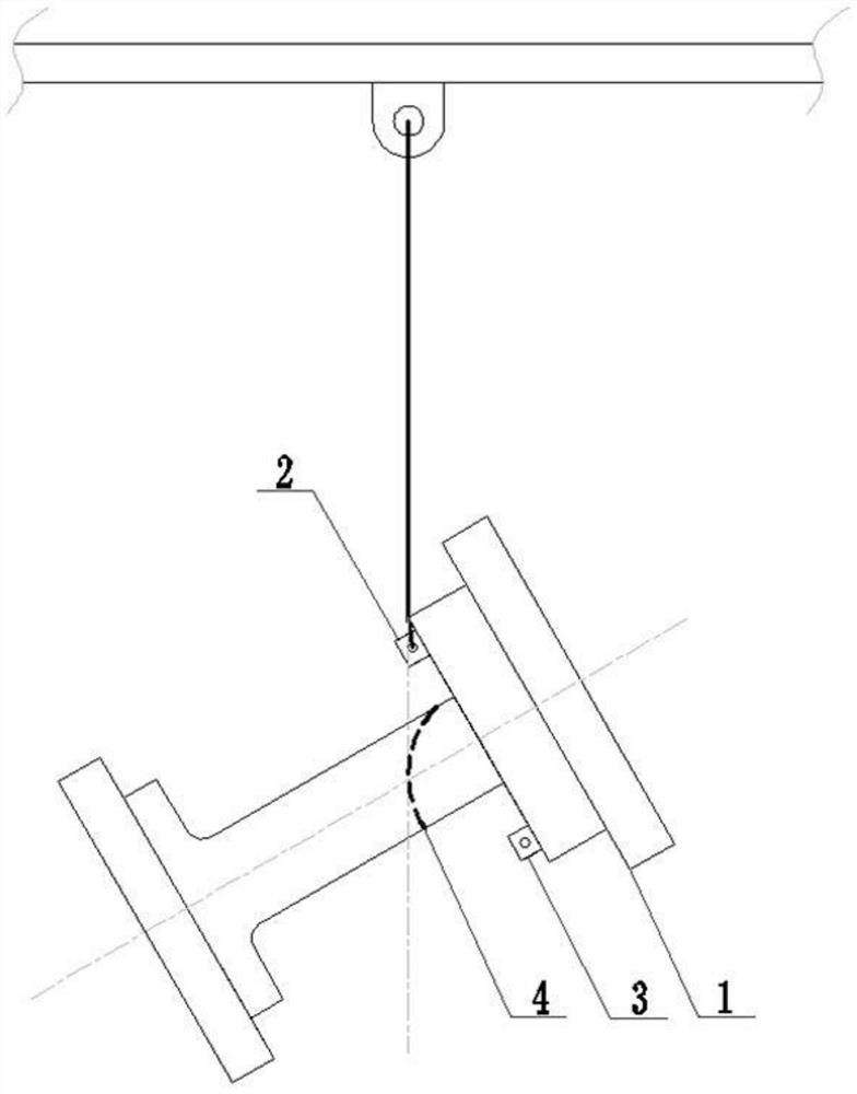
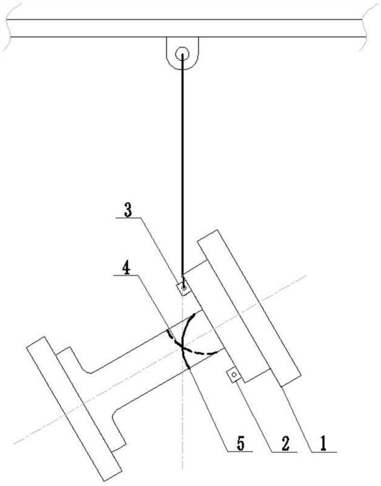
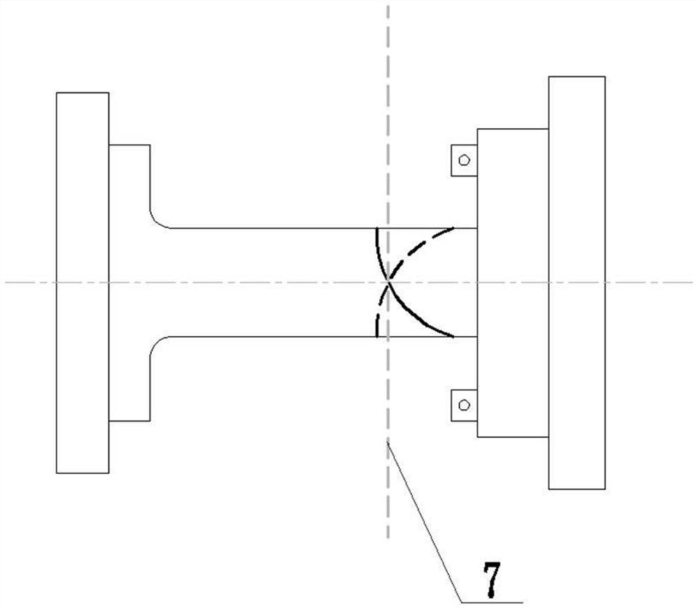

Image

  • Installing method of elastic coupling
  • Installing method of elastic coupling
  • Installing method of elastic coupling

Examples


Embodiment Construction

[0047] In order to better understand the technical solutions of the present invention, the embodiments of the present invention will be described in detail below in conjunction with the accompanying drawings.

[0048] It should be clear that the described embodiments are only some of the embodiments of the present invention, not all of them. Based on the embodiments of the present invention, all other embodiments obtained by persons of ordinary skill in the art without creative efforts fall within the protection scope of the present invention.

[0049] The present application will be described in further detail below through specific embodiments and in conjunction with the accompanying drawings.

[0050] In the description of this application, unless otherwise clearly specified and limited, the terms "first" and "second" are only used for the purpose of description, and cannot be understood as indicating or implying relative importance; unless otherwise specified or stated , ...


PUM


Abstract

The invention discloses an installing method of an elastic coupling. The installing method is characterized in that the elastic coupling is transported to an installing position through a traction trolley, the construction problem that the elastic coupling cannot be hoisted by welding a hoisting ring due to space limitation is solved, meanwhile, the installing hidden danger during the hoisting of the elastic coupling is also reduced, the tedious construction steps that due to the fact that no hull structure backing is arranged above the installation position of the elastic coupling, hull ribs need to be locally cut, and hanging beams need to be welded are avoided, and damage to the hull structure is greatly reduced.

Description

technical field [0001] The invention relates to the technical field of shipbuilding, in particular to an installation method of an elastic coupling. Background technique [0002] Elastic couplings are widely used in marine power devices, and are installed at the output end of marine diesel engines. The center displacement plays the role of vibration reduction and noise reduction, so as to protect the operating reliability of marine diesel engines, gearboxes and the entire transmission device. [0003] The elastic coupling needs to be installed after the alignment between the marine diesel engine and the gearbox is completed. Therefore, before the alignment of the marine diesel engine and the gearbox is completed, the elastic coupling needs to be pre-embedded in the engine room and hoisted after the alignment is completed. . According to the actual situation on site, it was found that the air intake pipeline and the supercharger of the main engine are above the installation...

Claims


Application Information

Patent Timeline
Patent Type & Authority Applications(China)
IPC IPC(8): B66C7/00B66C11/00B66C13/08B63B73/30
CPCB66C7/00B66C11/00B66C13/08B63B73/30
Inventor 尹浩姚海
Owner HUDONG ZHONGHUA SHIPBUILDINGGROUP
Learn More