Backlight module with high brightness and controllable light emitting spread angle

A backlight module, high-brightness technology, applied in optics, nonlinear optics, instruments, etc., can solve the problems of over-bright area and overlap, and achieve the effect of uniform light output and good display comfort.

Pending Publication Date: 2021-12-31
深圳市锐思华创技术有限公司
View PDF0 Cites 0 Cited by
  • Summary
  • Abstract
  • Description
  • Claims
  • Application Information

AI Technical Summary

Problems solved by technology

[0004] First, in order to allow the light source to fully cover the display AA area, the light from the light source adjacent to the light-emitting unit will partially overlap, so that a visually unavoidable overbright area will be produced;

Method used


Image

  • Backlight module with high brightness and controllable light emitting spread angle
  • Backlight module with high brightness and controllable light emitting spread angle
  • Backlight module with high brightness and controllable light emitting spread angle

Examples


Embodiment

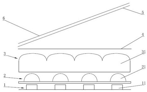
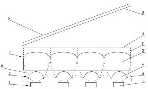
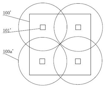
[0028] Such as figure 1 , figure 2 , Figure 4 , figure 2 Among them, A is the light source light emitted by the LED light-emitting unit, B is the light source light gathered by the spherical convex lens, and C is the light source light cut by the square convex lens, Figure 4 Among them, 101 is four LED light-emitting units, 100a is a rectangular light field respectively formed by four LED light-emitting units, 100 is a display area, a backlight module with high brightness and controllable light-emitting spread angle of the present invention, the backlight module The group includes a light source 1 arranged along the optical path, a first convex lens array 2, a second square convex lens array 3, a diffusion sheet 4, a diffusion sheet 2 5, and a TFT liquid crystal layer 6;

[0029] The light source 1 includes a plurality of LED light-emitting units 11 arranged in an array, the first convex lens array 2 includes a plurality of spherical convex lenses 21 matched with the p...


PUM


Abstract

The invention discloses a backlight module with high brightness and controllable light emitting spread angle. The backlight module comprises a light source, a first convex lens array, a second square convex lens array, a diffusion sheet I, a diffusion sheet II and a TFT liquid crystal layer which are arranged along a light path, wherein the light source comprises a plurality of LED light-emitting units arranged in an array mode, the first convex lens array comprises a plurality of spherical convex lenses matched with the LED light-emitting units, the second square convex lens array comprises a plurality of square convex lenses matched with the spherical convex lenses, the square convex lenses are arranged in an array mode and are sequentially connected in an adjacent mode, and the vertically downward projection of the square convex lens is rectangular; wherein the first convex lens array is arranged close to the light source. According to the backlight module, the convex lens array and the square convex lens array are arranged at the light source emergent end to collimate light rays of the light source, meanwhile, the two diffusion sheets are arranged, so that the backlight module is high in brightness and controllable in light emitting spread angle.

Description

technical field [0001] The invention relates to an optical display device, in particular to a backlight module in which a convex lens array and a square convex lens array are arranged at a light source output end to collimate light from a light source so as to realize high brightness and controllable spread angle of light. Background technique [0002] In the backlight module of traditional projection display, the light source is usually composed of multiple light-emitting units. A combined light source is formed by combining the light sources of the multiple light-emitting units, and the combined light source is projected onto the light-emitting surface to realize the backlight display. [0003] Such as image 3 , is a schematic diagram of the light-emitting principle of a traditional backlight module, 101' is four LED light-emitting units, 100a' is a circular light field formed by the four LED light-emitting units, and 100 is a display area, in order to take into account th...

Claims


Application Information

Patent Timeline
IPC IPC(8): G02F1/13357G03B21/00G03B21/20
CPCG02F1/133603G02F1/133606G02F1/133607G03B21/2033G03B21/206G03B21/006
Inventor 李灝王秀丞黄曙光卢睿王应君
Owner 深圳市锐思华创技术有限公司
Why Eureka
Try Eureka