
Circulating clarification equipment

A kind of equipment and cone technology, which is applied in the field of circulating clarification equipment, can solve the problems of low treatment efficiency, structural differences, and difficult dredging, and achieve the effects of low energy consumption, high water production capacity, and large cross-sectional area of ​​water

Pending Publication Date: 2021-12-31
温华环境科技(北京)有限公司
View PDF9 Cites 1 Cited by
  • Summary
  • Abstract
  • Description
  • Claims
  • Application Information

AI Technical Summary

Problems solved by technology

However, the mud accumulation area at the bottom is blocked by the upper structure in the overlapping area, making dredging difficult
In addition, due to structural differences in the water outlet areas on both sides, it is easy to have inconsistent water quality.
[0005] In short, in order to solve the problem of large footprint of water treatment equipment, the existing technology provides various solutions listed above, but these solutions still have the problems of low treatment efficiency and difficult sludge cleaning

Method used


Image

  • Circulating clarification equipment
  • Circulating clarification equipment
  • Circulating clarification equipment

Examples


Embodiment Construction

[0025] In order to have a clearer understanding of the technical features, purposes and effects of the present application, specific implementation methods of the present application will now be described with reference to the accompanying drawings. Wherein, the same parts adopt the same reference numerals.

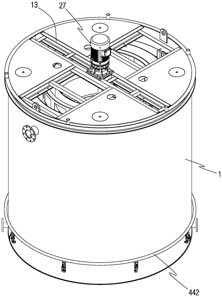
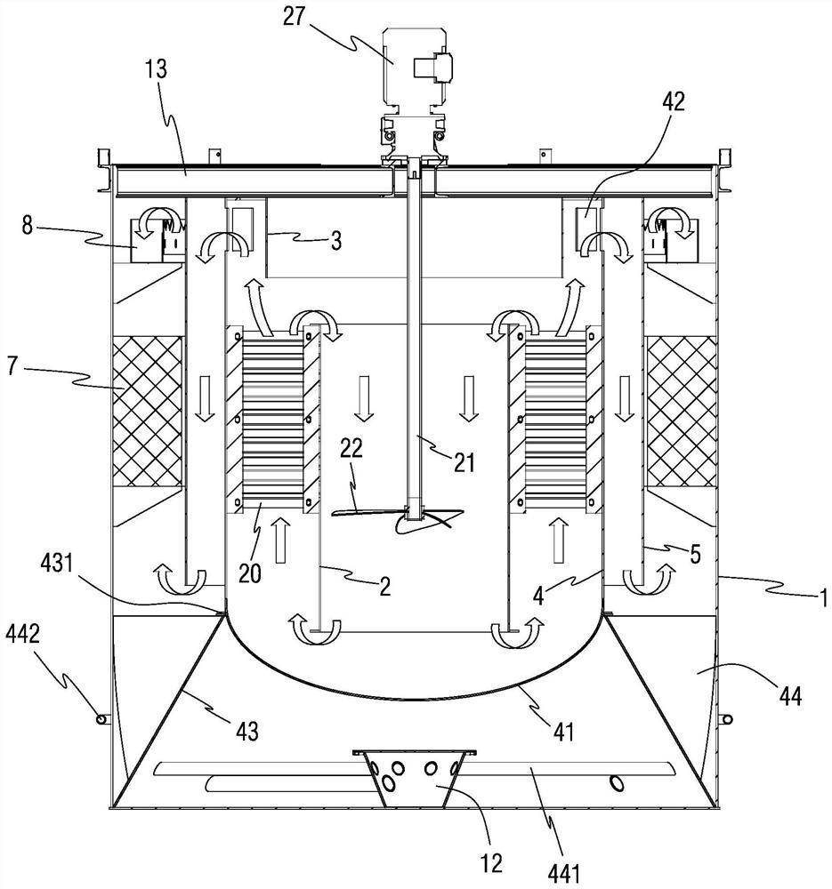
[0026] Such as Figure 1-3 As shown, the present application proposes a circular clarification device, which includes a cylindrical clarification tank 1 , and the entire water treatment process is carried out inside the clarification tank 1 . The floor area of ​​the entire equipment of the present application is determined by the diameter and height of the clarifier 1, so it is easy to set a reasonable size range according to the constraints of road transportation, which is convenient for saving transportation costs and improving the competitiveness of products.

[0027] When the diameter and height of the clarification tank 1 are limited, it is necessary to consider inc...


PUM

PropertyMeasurementUnit
angleaaaaaaaaaa

Abstract

The invention discloses circulating clarification equipment. The equipment comprises a cylindrical clarifying barrel, wherein a flow guide barrel, wherein a flow dividing barrel, a flocculation barrel and a flow pushing barrel are coaxially arranged in the clarifying barrel, and the diameters of the flow guide barrel, the flow dividing barrel, the flocculation barrel and the flow pushing barrel are sleeved from small to large; wherein the shunting cylinder is arranged above the guide cylinder, and both the shunting cylinder and the guide cylinder are arranged in the flocculation barrel; the lower part of the flocculation barrel is sealed by an arc-shaped bottom, and windows communicated with the plug flow barrel are uniformly formed in the circular side wall of the upper part in a surrounding manner; stirring blades are arranged in the guide cylinder and are fixed on the inner side wall of the flocculation barrel through a plurality of connecting plates on the outer side wall. According to the circulating clarification equipment, a coaxial five-cylinder layout structure is adopted, the annular water passing channel can be formed on the periphery of each cylinder. Compared with a pipeline or a single-side water passing structure of a rectangular pool in the prior art, the annular water passing channel has the largest water passing sectional area under the same volume and highest water production capacity per unit volume, and the energy consumption per unit water yield can be controlled to be lower.

Description

technical field [0001] The application relates to a sewage treatment equipment, in particular to a circulating clarification equipment with compact structure, small footprint and high treatment efficiency. Background technique [0002] The clarifier is a device for coagulating water and removing suspended solids and colloids in water. The coagulation treatment process of sewage includes three stages: mixing of water and chemicals, reaction and separation of flocs and water. The clarifier is a special equipment that completes the above three processes in one. Existing water treatment equipment is usually composed of sedimentation tanks, coagulation tanks, flocculation tanks, clarification tanks, etc. The sewage is processed through the above-mentioned pools in sequence, and the added chemicals such as coagulants, flocculants, etc. The harmful components of the waste water are transformed into solids and settle to the bottom of the pond, and finally clear water that meets th...

Claims


Application Information

Patent Timeline
Patent Type & Authority Applications(China)
IPC IPC(8): C02F1/52
CPCC02F1/5281C02F2201/002C02F2201/003C02F2201/004C02F2303/14
Inventor 汤波华英豪陈义娇易军王健郑心愿段红平张湛张继方史红伟
Owner 温华环境科技(北京)有限公司
Learn More