Rotary bottle blowing machine bottom die structure for medical infusion bottle production

A rotary blow molding machine technology, applied in the field of blow molding machines, can solve the problems of long trial period, cumbersome parts replacement, sticking together, etc., and achieve the effect of improving product qualification rate and precise positioning

Active Publication Date: 2021-12-31
SONGYUAN MACHINERY MFG
View PDF7 Cites 0 Cited by
  • Summary
  • Abstract
  • Description
  • Claims
  • Application Information

AI Technical Summary

Problems solved by technology

The medical hanging bottle is generally blow molded by a rotary blow molding machine. After forming, there will be a material head and a hanging ring at the bottom of the medical hanging bottle. The existing rotary blow molding machine has no freely adjustable guide rod at the center of the bottom mold. On the one hand, during the mold trial process, due to factors such as poor fit between the suspension ring and the bottom of the bottle, accumulation of material at the bottom of the bottle, poor molding of the bottom of the bottle, and convex bottom, it is necessary to continuously replace parts and try again. The cycle is long, and on the other hand, the relative height between the material head and the suspension ring cannot be changed, which cannot meet the diverse production needs of medical suspension bottles
The temperature of the plastic preform is high after blow molding in the mold, and the bottle body and the bottom of the bottle are soft. Therefore, the bottom mold of the traditional bottle blowing mold tends to stick to the bottom part of the bottle. After the mold is opened, the bottle will follow the bottom mold Walking, resulting in difficulty in demoulding the bottom of the bottle, prone to deformation, and low product qualification rate

Method used


Image

  • Rotary bottle blowing machine bottom die structure for medical infusion bottle production
  • Rotary bottle blowing machine bottom die structure for medical infusion bottle production
  • Rotary bottle blowing machine bottom die structure for medical infusion bottle production

Examples


Embodiment Construction

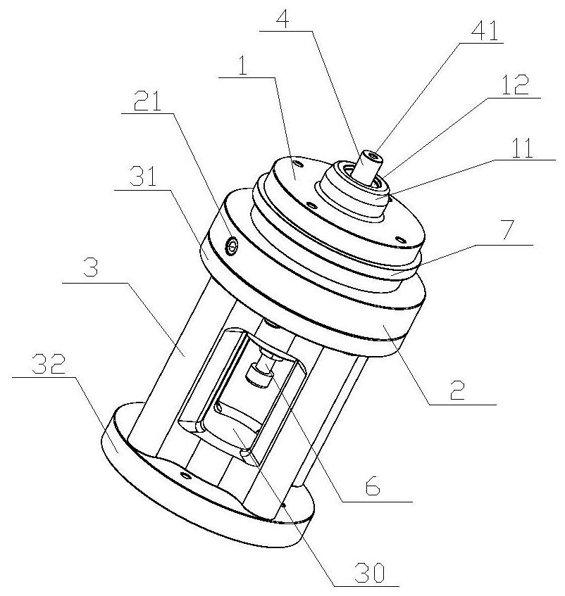
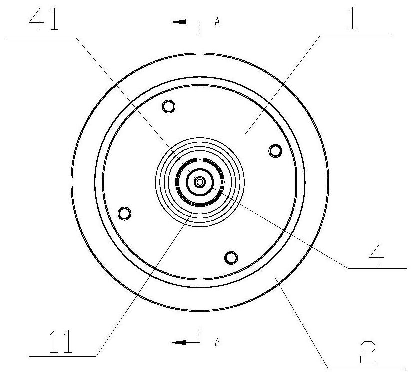
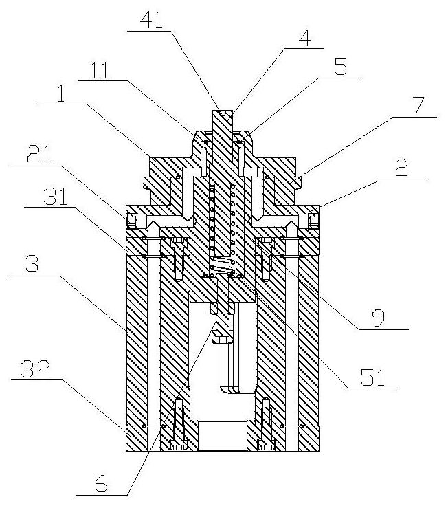
[0030] refer to Figure 1 to Figure 13 , this embodiment provides a bottom mold structure of a rotary blow molding machine for the production of medical hanging bottles, including a bottom mold 1, a water sealing plate 2, a support frame 3, a cooling core 5, a guide rod 4 and a jacking mechanism 6, The bottom mold 1 is installed on the water sealing plate 2, and the water sealing plate 2 is installed on the support frame 3. The upper end of the bottom mold 1 extends upwards out of the hanging bottle support part 11, and the upper end of the hanging bottle supporting part 11 is provided with a ring groove 12, and the hanging ring The groove 12 is connected with the guide hole, the upper and lower ends of the cooling core 5 are respectively installed inside the bottom mold 1 and the water sealing plate 2, the inside of the cooling core 5 is provided with a cavity 51 with the upper and lower ends open, and the guide rod 4 is installed in the cavity 51 and can move up and down alo...


PUM


Abstract

The invention discloses a rotary bottle blowing machine bottom die structure for medical infusion bottle production. The structure comprises a bottom die, a water sealing plate, a supporting frame, a cooling core, a guide rod and a jacking mechanism, the bottom die, the water sealing plate and the supporting frame are mounted in sequence, the upper end of the bottom die extends upwards to form an infusion bottle supporting part with a hanging ring groove and a guide hole, the cooling core is mounted in the bottom die and the water sealing plate, a cavity with the upper end being open is formed in the cooling core, the guide rod is movably mounted in the cavity, a positioning hole is formed in the upper end of the guide rod, the guide rod and the water sealing plate are connected through springs, the upper end of the jacking mechanism penetrates through the water sealing plate, moves up and down along the cavity and can abut against the guide rod after moving upwards, and forward adjustment of the length of the guide rod extending out of the bottom die is achieved by adjusting the length of the upper end of the jacking mechanism extending into the cavity. The rotary bottle blowing machine bottom die structure has the advantages that the length of the guide rod extending out of the bottom die can be quickly adjusted to better meet the infusion bottle production requirement, bottle bottoms are prevented from sticking to the die, and hanging rings at the bottom of infusion bottles and material heads are accurately positioned and are not prone to deviating from the centers of the bottle bottoms in the blow molding process.

Description

【Technical field】 [0001] The invention belongs to the technical field of bottle blowing machines, and in particular relates to a bottom mold structure of a rotary bottle blowing machine for the production of medical hanging bottles. 【Background technique】 [0002] The medical suspension bottle is a plastic bottle with a suspension ring at the bottom. When in use, the suspension ring can be folded up to realize the upside-down use of the medical suspension bottle. The medical hanging bottle is generally blow molded by a rotary blow molding machine. After forming, there will be a material head and a hanging ring at the bottom of the medical hanging bottle. The existing rotary blow molding machine has no freely adjustable guide rod at the center of the bottom mold. On the one hand, during the mold trial process, due to factors such as poor fit between the suspension ring and the bottom of the bottle, accumulation of material at the bottom of the bottle, poor molding of the bott...

Claims


Application Information

Patent Timeline
Patent Type & Authority Applications(China)
IPC IPC(8): B29C49/70B29C49/64B29C49/48B29L22/00
CPCB29C49/70B29C49/64B29C49/4823B29C2049/4825B29L2022/00B29C2049/701
Inventor 李坤文刘昕宇胡洋杜秀萍钱叶波丁才见齐兴浩
Owner SONGYUAN MACHINERY MFG
Why Eureka
Try Eureka