
Split valve stent and interventional mitral valve replacement system comprising same

A split-type, mitral valve technology, applied in the field of medical devices, can solve the problems of inability to meet the TMVR technology, valve stent displacement, etc., and achieve the effect of easy operation and low valve angle height

Pending Publication Date: 2021-12-31
SHANGHAI CINGULAR BIOTECH
View PDF2 Cites 1 Cited by
  • Summary
  • Abstract
  • Description
  • Claims
  • Application Information

AI Technical Summary

Benefits of technology

This new type of heart valves has two parts - one part that controls blood flow while another part helps with its operation. These components work together smoothly by being inserted into different ways along their way inside the patient's vasculature before they have been secured secure enough during surgery. Additionally, this technology allows for precise placement without requiring invasive procedures like open chest surgeries.

Problems solved by technology

This technical problem addressed in this patents relates to finding a better solution for delivering prosthetic cardiac valves without compromise caused by their larger sizes during placement compared to traditional ones.

Method used


Image

  • Split valve stent and interventional mitral valve replacement system comprising same
  • Split valve stent and interventional mitral valve replacement system comprising same
  • Split valve stent and interventional mitral valve replacement system comprising same

Examples


Embodiment Construction

[0075] It should be understood that in the description of the present invention, the terms "center", "longitudinal", "transverse", "upper", "lower", "front", "rear", "left", "right", " The orientations or positional relationships indicated by "vertical", "horizontal", "top", "bottom", "inner" and "outer" are based on the orientations or positional relationships shown in the drawings, and are only for the convenience of describing the present invention and Simplified descriptions, rather than indicating or implying that the device or element referred to must have a particular orientation, be constructed and operate in a particular orientation, and thus should not be construed as limiting the invention. In addition, the terms "first", "second", etc. are used for descriptive purposes only, and should not be understood as indicating or implying relative importance or implicitly specifying the quantity of the indicated technical features. Thus, a feature defined as "first", "second...


PUM

PropertyMeasurementUnit
Angleaaaaaaaaaa
Widthaaaaaaaaaa
Radianaaaaaaaaaa

Abstract

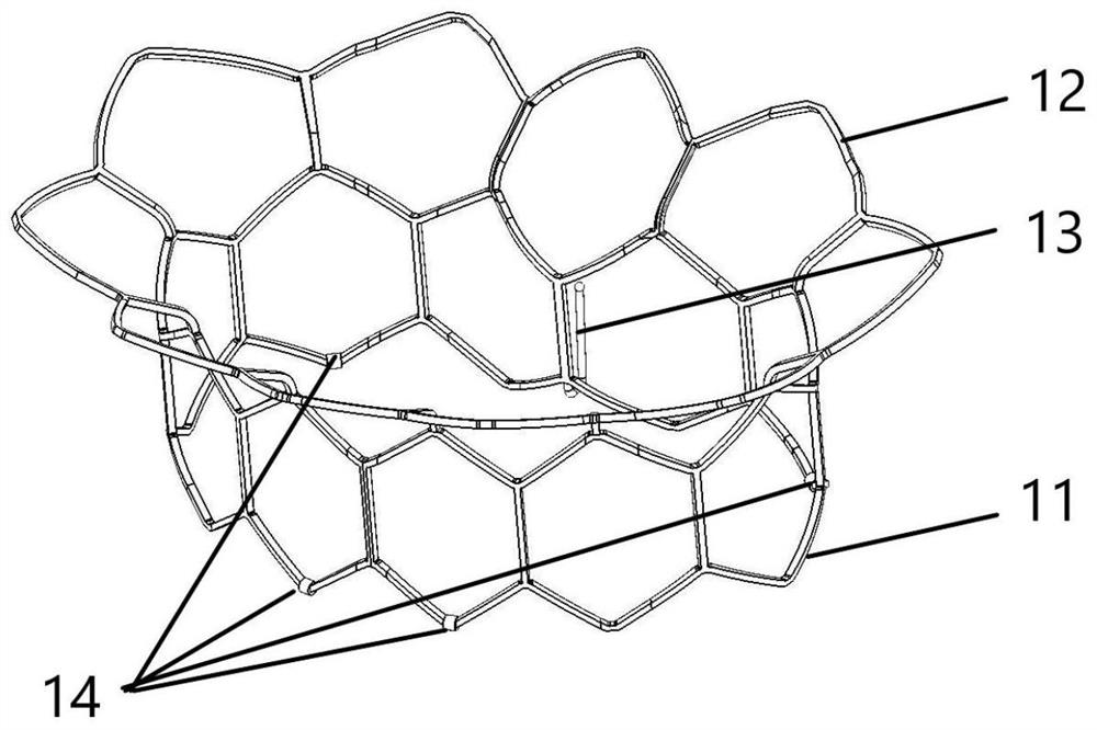
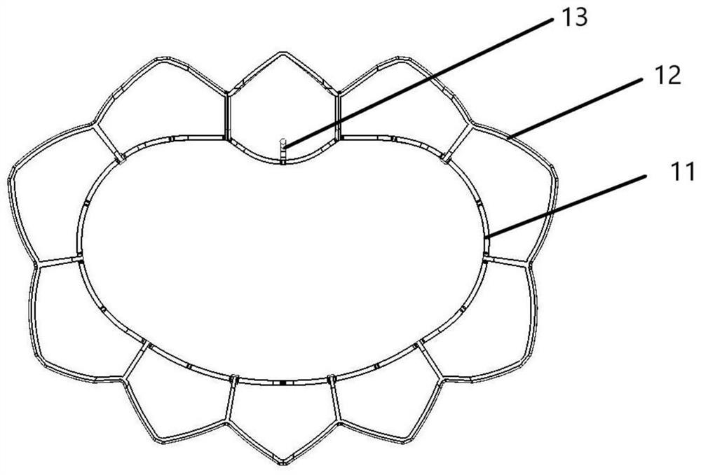
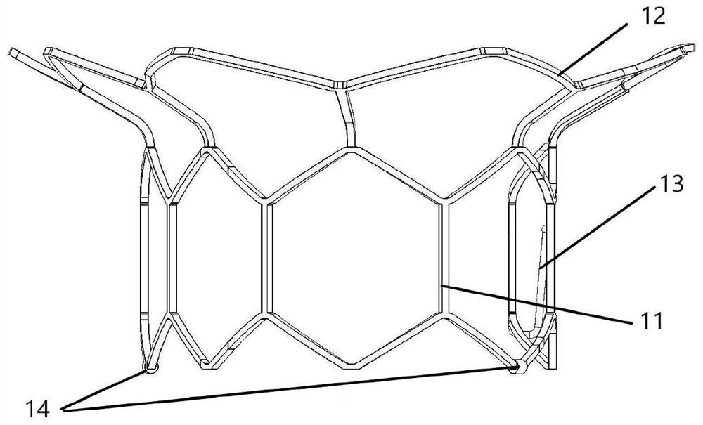
The invention provides a split valve stent and an interventional mitral valve replacement system comprising the same. The split valve stent comprises an outer frame and an inner frame arranged in the outer frame and matched with the outer frame; the outer frame comprises a cylindrical outer metal frame with a kidney-shaped section, one end of the outer metal frame is folded outwards in the circumferential direction to form a supporting ring, and at least one hook is arranged at the kidney-shaped concave position of the other end of the outer metal frame; the inner frame comprises a cylindrical inner metal frame with a kidney-shaped section, two connecting wires which are crossed in an X shape are arranged at one end of the inner metal frame, and the interface of the end of the inner metal frame is cut into an 8 shape by the two connecting wires; and when the outer frame is in the unfolded state, the side, provided with the supporting ring, of the outer frame is reversely buckled to a valve ring on one side of the left atrium, the side, provided with the hook, of the outer frame extends into the left ventricle, and when the inner frame is in the unfolded state, the side, not provided with the connecting wire, of the inner frame faces the left atrium, and the side, provided with the connecting wire, of the inner frame extends into the left ventricle.

Description


Claims


Application Information

Patent Timeline
Owner SHANGHAI CINGULAR BIOTECH
Learn More