Pressure regulating spring

A technology of pressure-regulating springs and spring holes, applied in springs, springs/shock absorbers, coil springs, etc., can solve the problem that the pressure-regulating springs are difficult to accurately control the pressure-regulating springs, and achieve the effect of precise pressure regulation

Active Publication Date: 2021-12-28
JIANGSU HENGLI SPRING
View PDF14 Cites 0 Cited by
  • Summary
  • Abstract
  • Description
  • Claims
  • Application Information

AI Technical Summary

Problems solved by technology

[0003] In the process of realizing the present invention, it is found that at least the following problems in the prior art have not been solved: the current pressure regulating device of the shock absorbing system needs to use a pressure regulating spring, which is sleeved on the screw rod, and can be adjusted by rotating the pressure regulating spring. Pressure nut, the pressure regulating nut compresses the pressure regulating spring to realize the pressure adjustment of the shock absorbing system, but this kind of pressure regulating spring is difficult to accurately control the pressure regulating spring

Method used

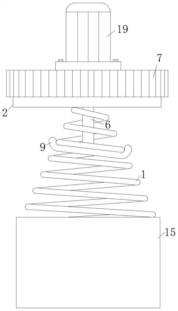
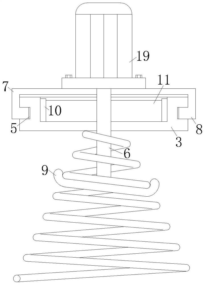
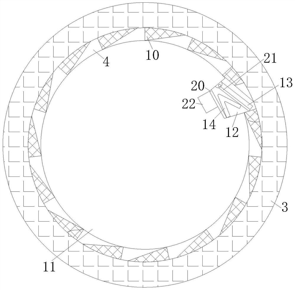

Image

  • Pressure regulating spring
  • Pressure regulating spring
  • Pressure regulating spring

Examples


Embodiment Construction

[0032] The technical solutions of the present invention will be clearly and completely described below in conjunction with the embodiments. Obviously, the described embodiments are part of the embodiments of the present invention, but not all of them. Based on the embodiments of the present invention, all other embodiments obtained by persons of ordinary skill in the art without making creative efforts belong to the protection scope of the present invention.

[0033] In describing the present invention, it is to be understood that the terms "center", "longitudinal", "transverse", "length", "width", "thickness", "upper", "lower", "front", " Back", "Left", "Right", "Vertical", "Horizontal", "Top", "Bottom", "Inner", "Outer", "Clockwise", "Counterclockwise", etc. or The positional relationship is based on the orientation or positional relationship shown in the drawings, which is only for the convenience of describing the present invention and simplifying the description, rather t...


PUM


Abstract

The invention provides a pressure adjusting spring. The spring comprises a spring body, a pressure adjusting mechanism is arranged above the spring body, the pressure adjusting mechanism comprises a base plate, the bottom end of the base plate is fixedly connected with the top end of the spring body, a movable bin is formed in the top of the base plate, a ring groove is formed in the side edge of the base plate, an extension rod vertically penetrates through the interior of the base plate, a rotary cover is fixedly connected to the position, located above the base plate, of the top end of the extension rod, the outer surface of the base plate is connected with the rotary cover in a sleeving mode, a limiting ring is fixedly connected to the lower end of the inner surface of the rotary cover, one end, located in the movable bin, of the extension rod penetrates through the rotary cover to be connected with an output shaft of a motor, the extension rod and the limiting rod fixed to the bottom end of the extension rod can be driven when the motor is started, in the limiting rod rotating process, the upper end of the spring body is folded and extruded between the limiting rod and the base plate, and therefore pressure adjusting of the spring is achieved, and accurate pressure adjusting can be achieved by folding the spring bodies of different lengths.

Description

technical field [0001] The invention relates to the technical field of springs, in particular to a pressure regulating spring. Background technique [0002] Spring is a mechanical part that uses elasticity to work. It is generally made of spring steel to control the movement of parts, alleviate shock or vibration, store energy, measure force, etc. It is widely used in machines and instruments. [0003] In the process of realizing the present invention, it is found that at least the following problems in the prior art have not been solved: the current pressure regulating device of the shock absorbing system needs to use a pressure regulating spring, which is sleeved on the screw rod, and can be adjusted by rotating the pressure regulating spring. Press the nut, and the pressure regulating nut compresses the pressure regulating spring to realize the pressure regulation of the damping system, but it is difficult for this kind of pressure regulating spring to accurately control ...

Claims


Application Information

Patent Timeline
Patent Type & Authority Applications(China)
IPC IPC(8): F16F1/08F16F1/12F16D41/14
CPCF16F1/08F16F1/12F16F1/121F16F1/122F16D41/14Y02E10/72
Inventor 王刘恩计翔宇
Owner JIANGSU HENGLI SPRING
Why Eureka
Try Eureka