A pressure differential plunger automatic pressure regulating valve

An automatic pressure regulation and plunger technology, applied in the field of pressure regulating valves, can solve the problems of low adjustment accuracy, incomplete application of liquid media, single function, etc., and achieve the effect of rapid and accurate control

Active Publication Date: 2017-07-18
成都卡斯特精密铸造有限公司
View PDF8 Cites 0 Cited by
  • Summary
  • Abstract
  • Description
  • Claims
  • Application Information

AI Technical Summary

Problems solved by technology

However, this kind of pressure regulating valve is mainly used for the circulation of gas medium, and it is not completely suitable for liquid medium. Moreover, this kind of pressure reducing valve type pressure regulating valve has low adjustment accuracy, and can only decompress high-pressure fluid medium. single

Method used


Image

  • A pressure differential plunger automatic pressure regulating valve

Examples


Embodiment Construction

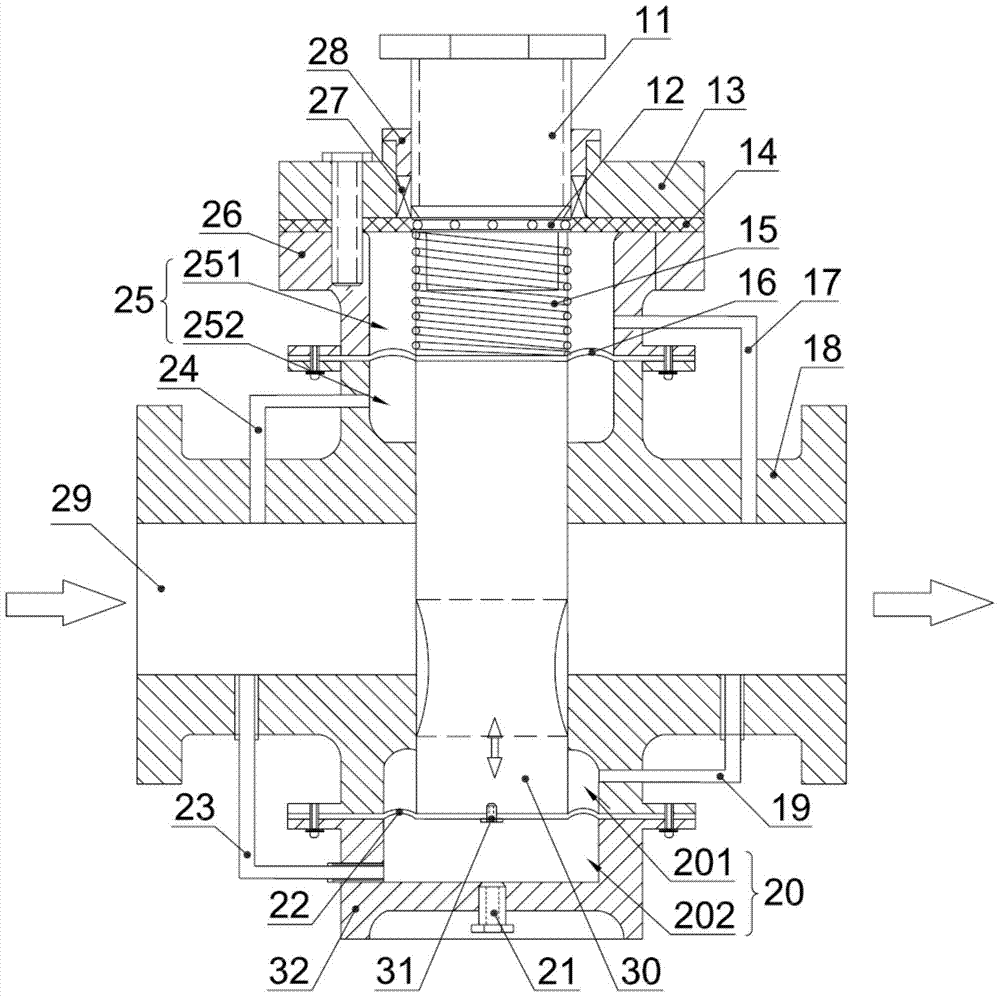
[0019] refer to figure 1 , a pressure differential plunger automatic pressure regulating valve, including a valve body 18, a medium passage 29 located in the valve body 18, and a plunger body 30 arranged in the valve body 18 and intersecting with the medium passage 29, the plunger body 30 The upper valve body 18 is provided with an upper chamber 25, the upper chamber 25 is provided with an upper diaphragm 16, and the upper diaphragm 16 divides the upper chamber 25 into a first upper chamber 251 at the upper part of the upper diaphragm 16, And the second upper chamber 252 at the bottom of the upper diaphragm 16, the lower surface of the upper diaphragm 16 is fixedly connected with the upper end surface of the plunger body 30, and the upper surface of the upper diaphragm 16 is fixedly connected with an elastic member 15, and the elastic member 15 is preferably It is a spring, and the other end of the elastic member 15 is connected with a relatively rotatable pressure-adjusting b...


PUM


Abstract

The invention discloses a differential pressure plunger automatic pressure regulating valve. The differential pressure plunger automatic pressure regulating valve comprises a valve body, a medium channel and a plunger. An upper cavity is arranged in the position, on the upper portion of the plunger, of the valve body; an upper membrane is arranged in the upper cavity and divides the upper cavity into a first upper cavity located on the upper portion of the upper membrane and a second upper cavity located on the lower portion of the upper membrane; the lower surface of the upper membrane is fixedly connected with the upper end face of the plunger; the upper surface of the upper membrane is fixedly connected with an elastic component; the other end of the elastic component is connected with a pressure regulating bolt capable of rotating relatively; a first connection channel for communicating the first upper cavity with the medium channel at the outlet end is arranged between the first upper cavity and the medium channel at the outlet end; a second connection channel for communicating the second upper cavity with the medium channel at the inlet end is arranged between the second upper cavity and the medium channel at the inlet end. The differential pressure plunger automatic pressure regulating valve is of the upper-and-lower-stage outlet end pressure feedback response design, response is more sensitive, and control is more accurate.

Description

technical field [0001] The invention belongs to the technical field of pressure regulating valves, in particular to an automatic pressure regulating valve with a differential pressure plunger. Background technique [0002] The pressure regulating valve is used in various water supply systems, heating systems, fire protection systems, etc., to clamp the pressure of the fluid medium at a certain threshold to ensure pressure balance and safe use. The general pressure regulating valve is mostly a throttle valve, and the flow adjustment is realized by manually adjusting the pore size of the flow channel, so as to realize the pressure adjustment. Obviously, this method cannot realize the automatic adjustment of the pressure, and the reliability is not high. The other is the pressure reducing valve type pressure regulating valve, which mainly detects the pressure through the diaphragm. When the pressure is too high, the diaphragm moves upward, driving the valve core to adjust the s...

Claims


Application Information

Patent Timeline
Patent Type & Authority Patents(China)
IPC IPC(8): F16K17/30
CPCF16K17/30
Inventor 付明
Owner 成都卡斯特精密铸造有限公司
Why Eureka
Try Eureka