
Engine crankshaft forging die for hydrogen fuel cell hybrid power system

A hybrid power system and fuel cell technology, applied in the field of crankshaft forging, can solve problems such as the influence of the continuity of the crankshaft forging process

Inactive Publication Date: 2021-12-28
XIHUA UNIV
View PDF6 Cites 0 Cited by
  • Summary
  • Abstract
  • Description
  • Claims
  • Application Information

AI Technical Summary

Problems solved by technology

[0003] The mold used in crankshaft forging is usually divided into upper and lower parts to facilitate the cooling and removal of the formed crankshaft. However, in the prior art, the upper mold of the crankshaft mold is difficult to quickly separate from the lower mold, so the continuity of the crankshaft forging process is greatly affected. Therefore, the present invention provides an engine crankshaft forging die for a hydrogen fuel cell hybrid power system, which can quickly realize the disassembly and separation of the upper die to solve the above problems

Method used


Image

  • Engine crankshaft forging die for hydrogen fuel cell hybrid power system
  • Engine crankshaft forging die for hydrogen fuel cell hybrid power system
  • Engine crankshaft forging die for hydrogen fuel cell hybrid power system

Examples


Embodiment 1

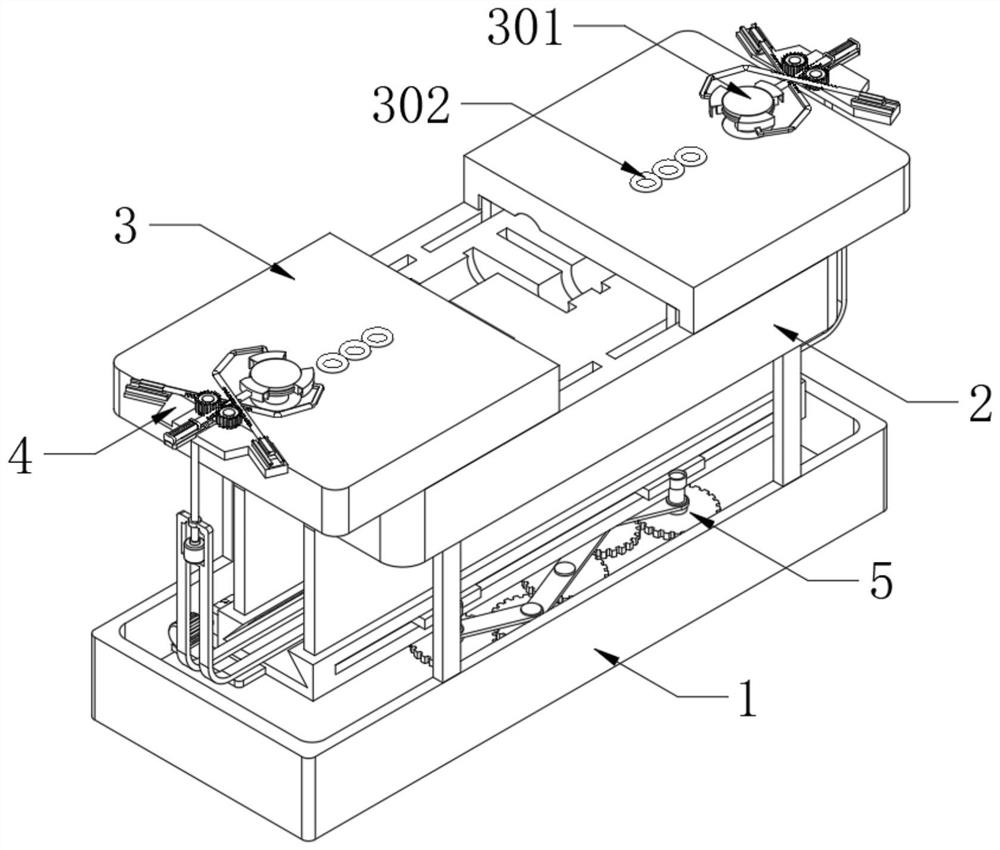
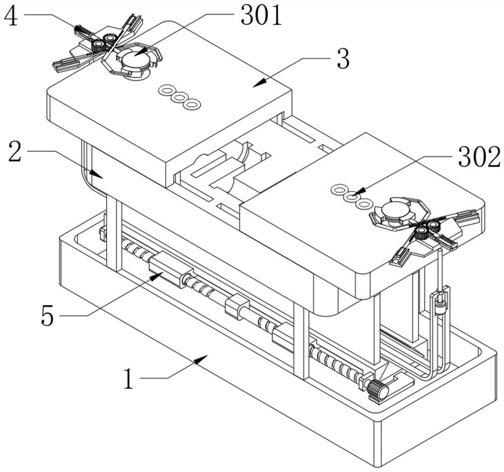
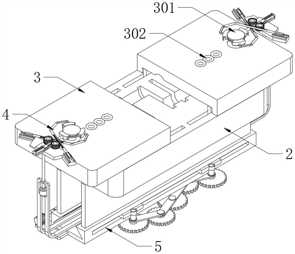
[0037] see Figure 1-3 , an engine crankshaft forging die for a hydrogen fuel cell hybrid power system, comprising an upper die 3 and a lower die 2, the upper die 3 is divided into two parts, the two parts of the upper die 3 are respectively movably connected with the upper side of the lower die 2, and the upper die 3 is provided with a sealable injection hole 302; the upper edge of the upper mold 3 is fixedly connected with a positioning column 301, and the outer side of the positioning column 301 is matched with a positioning component 4, and the lower side of the positioning component 4 is connected to the installation box 1 through a transverse adjustment member 5 above;

[0038] In the present invention, by setting the upper mold 3 and the lower mold 2, when the device is used for crankshaft forging, the required molding material is first poured into the forming groove of the lower mold 2, and then the lateral adjustment member 5 cooperates with the positioning assembly 4...

Embodiment 2

[0040] Such as Figure 4-8 As shown, the differences based on Embodiment 1 are:

[0041] The lateral adjustment member 5 includes a mounting rail 501, which is fixedly connected to the inner bottom surface of the mounting box 1, and the two ends of the lower side of the lower mold 2 are respectively fixedly connected to the upper side of the mounting rail 501 through a mounting plate; the mounting rail 501 is provided with a traverse groove 503, two traversing sliders 502 are slidably connected in the traversing groove 503;

[0042] The outer end of the traversing slider 502 is fixedly connected with a support plate 504, and the upper end of the support plate 504 is fixedly connected with an adjustment cylinder 505; The upper end of the plate 504 is slidingly connected;

[0043] An extension block A510 and an extension block B511 are fixedly connected to both sides of the traversing slider 502 respectively. Both sides of the installation rail 501 are provided with a through ...

Embodiment 3

[0050] Such as Figure 9-11 , based on Embodiment 1-2, the difference is:

[0051] The positioning assembly 4 includes a positioning slide rail A401, a positioning slide rail B402 and a positioning slide rail C403. The positioning slide rail A401, the positioning slide rail B402 and the positioning slide rail C403 are all fixedly connected to the mounting frame 6, and the lower side of the mounting frame 6 is fixedly connected to the The upper end of the adjustment cylinder 505; the upper side of the positioning slide rail A401, the positioning slide rail B402 and the positioning slide rail C403 are all slidably connected with the sliding block 404, the positioning slide rail C403 is fixedly connected with the drive cylinder 410, and the output end of the drive cylinder 410 is fixedly connected with a gear Bar bar 409; the lower side of the connection between the output end and the rack bar 409 is fixedly connected with a sliding part 4032, and the lower side of the positionin...


PUM


Abstract

The invention discloses an engine crankshaft forging die for a hydrogen fuel cell hybrid power system, and belongs to the technical field of crankshaft forging. The engine crankshaft forging die for the hydrogen fuel cell hybrid power system comprises an upper die body and a lower die body, the upper die body is divided into two parts, the two parts of the upper die body are movably connected with the upper side of the lower die body respectively, and a sealable injection hole is formed in the upper die body; a positioning column is fixedly connected to the edge of the upper side of the upper die body, a positioning assembly is arranged at the outer side of the positioning column in a matched mode, and the lower side of the positioning assembly is connected to the upper portion of a mounting box through a transverse adjusting piece; the transverse adjusting part comprises a mounting rail, the mounting rail is fixedly connected to the inner bottom face of the mounting box, and the two ends of the lower side of the lower die body are fixedly connected to the upper side of a mounting rail through mounting plates correspondingly; and a transverse moving groove is formed in the mounting rail, and two transverse moving sliding blocks are connected into the transverse moving groove in a sliding mode. The engine crankshaft forging die solves the problem that in the prior art, an upper die body of a crankshaft forging die is difficult to disassemble and separate rapidly.

Description

technical field [0001] The invention relates to the technical field of crankshaft forging, in particular to an engine crankshaft forging die for a hydrogen fuel cell hybrid power system. Background technique [0002] The crankshaft is the main rotating part of the engine. After the connecting rod is installed, it can undertake the up and down reciprocating motion of the connecting rod into a circular rotating motion. It is an important part of the engine. Its material is made of carbon structural steel or ductile iron Made, there are two important parts: the main journal and the connecting rod neck; the main journal is installed on the cylinder block, the connecting rod neck is connected with the big end hole of the connecting rod, and the small head hole of the connecting rod is connected with the cylinder piston, which is a typical Crank slider mechanism; the lubrication of the crankshaft mainly refers to the lubrication of the connecting rod big end bearing bush and the c...

Claims


Application Information

Patent Timeline
Patent Type & Authority Applications(China)
IPC IPC(8): B21J13/02B21J13/08B21K1/08
CPCB21J13/02B21J13/085B21K1/08
Inventor 陈子龙杨继斌武小花曾令洲胡声洋肖丰牟森
Owner XIHUA UNIV
Learn More