
Hip joint implant with reshapeable fastening brackets

A technology of hip joints and implants, applied in the direction of joint implants, joint implants, hip joints, etc., which can solve problems that cannot be satisfactorily solved, lack of shape stability, etc.

Pending Publication Date: 2021-12-24
WALDEMAR LINK GMBH & CO
View PDF2 Cites 0 Cited by
  • Summary
  • Abstract
  • Description
  • Claims
  • Application Information

AI Technical Summary

Problems solved by technology

Pure titanium, however, is significantly easier to reshape, but is not used as standard for pot-shaped parts on the pelvic side due to lack of shape stability
This conflict of objectives has so far not been satisfactorily resolved

Method used


Image

  • Hip joint implant with reshapeable fastening brackets
  • Hip joint implant with reshapeable fastening brackets
  • Hip joint implant with reshapeable fastening brackets

Examples


Embodiment Construction

[0034] An embodiment of the hip implant according to the invention is in figure 1 The center is shown in the inserted state at the hip bone 9 (acetabulum).

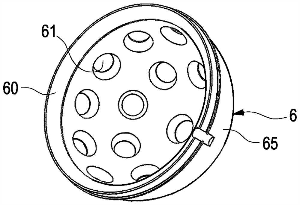
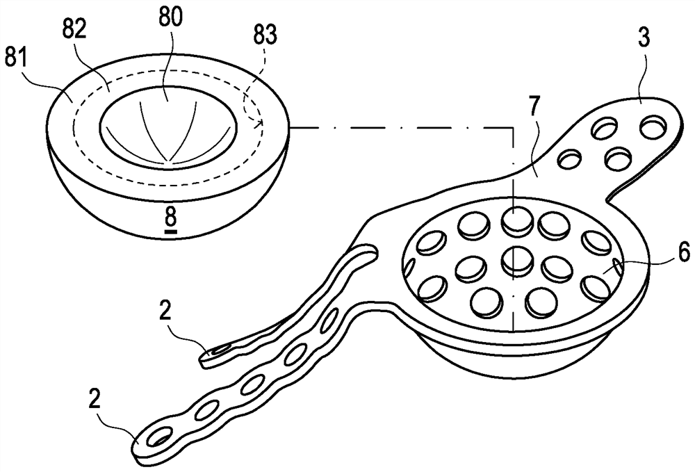
[0035] The hip joint implant is generally designated with reference numeral 1 and comprises a pot-shaped carrier 6 on which two flat and elongate fastening webs 2 are arranged pointing upwards (towards the cranium). On the pot-shaped carrier 6 (hereinafter also referred to as pot-shaped element for short), a shorter fastening web 3 extending downwards (towards the foot) is arranged opposite.

[0036] In the illustrated embodiment, the implant 1 consists of two parts, namely a pot 6 and a fixation part comprising fixation tabs 2, 3 and a fixation ring 4, the fixation tabs 2, 3 Arranged at the fixing ring. The fastening webs 2 are each elongated flat elements provided with a plurality of holes 21 for receiving fastening means. The fastening web 3 is likewise a flat element; however, in the exemplary embodiment shown it i...


PUM

PropertyMeasurementUnit
Tensile strengthaaaaaaaaaa

Abstract

The invention relates to a hip implant for fastening to a hip bone (9), comprising a carrier having a pot (6). The convex outer surface of the carrier is designed to rest on the hip bone (9) and at the concave inner side of the carrier has a receptacle for a pelvic-side support designed to receive an articular head of a femoral component of a hip prosthesis. The hip joint implant comprises outwardly directed flat fastening webs (2, 3) which are arranged on the edge region of the pot (6) and are each provided with at least one receptacle for a fastening means. The fastening webs (2, 3) are made of a reformable biocompatible material and are connected to the pot-shaped part (6) via a non-releasable material-fit connection (7), the pot-shaped part (6) being made of a further, more rigid biocompatible material. The high robustness of the pot (6) is thereby combined with an improved adaptation to the anatomical situation of the corresponding hip bone due to the redeformability. Fixation reliability, stability and long-term behavior are thus improved.

Description

technical field [0001] The present invention relates to a hip joint implant for fixation at the hip bone, said hip joint implant comprising a carrier with a pot, the convex outer surface of which is configured as For resting against the hip bone and having a receptacle for a pelvic-side bearing part at its concave inner side, the bearing part is configured to receive the joint head of the femoral part of the hip prosthesis, and the hip joint The implant comprises outwardly directed, flat fastening webs arranged on an edge region of the pot, each of which is provided with at least one receptacle for a fastening means. Furthermore, the invention relates to a manufacturing method for such a hip implant. Background technique [0002] The hip joint can degenerate due to disease or due to wear and tear. For the treatment of hip joints - endoprosthesis is tried and tested. The hip endoprosthesis comprises a femoral component which is implanted at the upper end of the femur and a...

Claims


Application Information

Patent Timeline
IPC IPC(8): A61F2/30A61F2/34A61F2/32
CPCA61F2/30749A61F2/34A61F2002/30014A61F2002/30578A61F2002/3241A61F2002/3401A61F2310/00023
Inventor H·D·林克H-J·费舍尔
Owner WALDEMAR LINK GMBH & CO
Learn More