A friction-driven pushing robot

A pusher robot, friction-driven technology, applied in conveyor objects, animal feeding devices, loading/unloading, etc., can solve the problems of insufficient pushing capacity, large front resistance, and insufficient push, and improve cleaning and pushing. effect, improve the ability to push, reduce the effect of omission

Active Publication Date: 2022-03-11
济南中科天睿科技有限公司
View PDF6 Cites 0 Cited by
  • Summary
  • Abstract
  • Description
  • Claims
  • Application Information

AI Technical Summary

Problems solved by technology

[0003] There are hygiene and timeliness problems in the method of manual timing pushing, and it is difficult to meet the needs of pushing; currently, pushing robots are mostly used for periodic pushing. The outside of the pushing robot is equipped with a rotatable cylinder, and the busbar surface of the cylinder is in contact with the feed. Push the feed to move to the position close to the fence, and under the friction between the cylinder and the feed, the cylinder can rotate around the axis, adapt to the movement of the pusher robot, and gradually push the feed located in front of the oblique side to the side; but this push method It is only applicable to the situation where the cylinder and the feed can generate a large friction force. For some loose and light feed, the contact position between the cylinder and the feed cannot provide enough friction for the cylinder to rotate. The capacity is insufficient, the push is not in place, and the pushed feed is scattered again. On the other hand, the cylinder cannot drive the feed to move sideways through rotation, causing the feed accumulated in the front to directly block the movement. Pressure pollution and other issues, it is difficult to meet the demand for pushing materials in livestock farms

Method used


Image

  • A friction-driven pushing robot
  • A friction-driven pushing robot
  • A friction-driven pushing robot

Examples


Embodiment 1

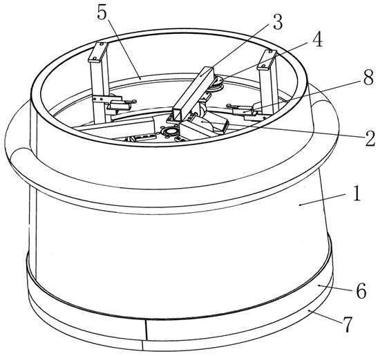
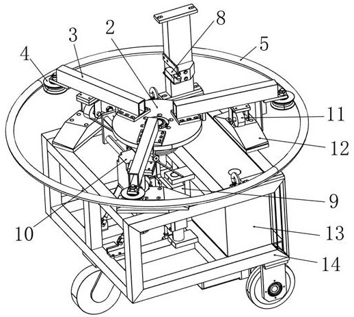
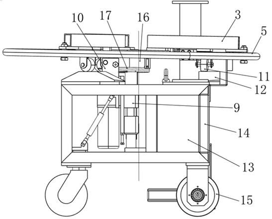
[0032] In a typical embodiment of the present invention, such as Figure 1-Figure 4 As shown, a friction-driven pushing robot is proposed.

[0033] Aiming at the problem that the current pusher robot is difficult to effectively push and stack loose and light feed, a friction-driven pusher robot is provided. The friction-driven rotating shell 1 is set to push and accumulate the feed. Surface to obtain friction to drive the rotating shell 1 to rotate, reduce the impact of feed contact cylinder friction on pushing efficiency, solve the problem of poor pushing efficiency of traditional pushing robots, and improve the ability to push scattered feed.

[0034] For the friction-driven pusher robot, it mainly includes a self-propelled platform, a rotating shell 1, a guide plate 2 and a lifting mechanism. The self-propelled platform is used as a whole mobile load-bearing structure, which drives the components installed on it to move as a whole, along the extension direction of the fence...


PUM


Abstract

The invention provides a friction-driven pusher robot; it relates to the field of animal husbandry equipment. In view of the problem that the current pusher robot is difficult to effectively push and stack loose and light feed, the feed is pushed and piled up by setting a friction-driven rotating shell, and the rotating shell is set obliquely so that The bottom end partially contacts the walking surface to obtain friction to drive the rotating shell to rotate, reduce the impact of feed contact cylinder friction on the pushing efficiency, and improve the ability to push scattered feed; including self-propelled platform, rotating shell and guide plate, rotating The shell is cylindrical and set outside the self-propelled platform. The inner wall of the rotating shell is provided with a circular guide rail. The guide disc is connected to the self-propelled platform through a spherical pair. The guide disc is connected with at least three sheaves. Rotary shell; the rotary shell, the guide plate and the circular guide rail are coaxially arranged, and the axis and the vertical direction are at a set angle, so that the bottom end surface of the rotary shell can partially contact the walking surface of the self-propelled platform to drive the rotary shell to rotate around the axis.

Description

technical field [0001] The invention relates to the field of animal husbandry equipment, in particular to a friction-driven material pushing robot. Background technique [0002] When feeding livestock in large-scale livestock farms, fodder such as pastures is piled up along the outside of the enclosure, and the head of the livestock sticks out of the fence to eat, but the feed will be pushed and scattered away from the fence during the feeding process, and the feed that is located in the distance needs to be continuously removed. Push close to the fence for easy feeding. [0003] There are hygiene and timeliness problems in the method of manual timing pushing, and it is difficult to meet the needs of pushing; currently, pushing robots are mostly used for periodic pushing. The outside of the pushing robot is equipped with a rotatable cylinder, and the busbar surface of the cylinder is in contact with the feed. Push the feed to move to the position close to the fence, and und...

Claims


Application Information

Patent Timeline
Patent Type & Authority Patents(China)
IPC IPC(8): B65G47/82B65G65/28A01K5/02
CPCB65G47/82B65G65/28A01K5/02
Inventor 赵延胜
Owner 济南中科天睿科技有限公司
Why Eureka
Try Eureka