Eureka AIR delivers breakthrough ideas for toughest innovation challenges, trusted by R&D personnel around the world.

Method and system automatically obtaining transformer area topological graph

A technology for automatic acquisition and topology map, which is applied in radio wave measurement systems, satellite radio beacon positioning systems, measurement devices, etc., and can solve problems such as no drawing, no faulty equipment, and topological maps without geographic location information. To achieve the effect of reducing errors and omissions and improving the success rate of collection

Inactive Publication Date: 2017-05-31
湖南华烨智能通信技术股份有限公司
View PDF7 Cites 15 Cited by
  • Summary
  • Abstract
  • Description
  • Claims
  • Application Information

AI Technical Summary

Problems solved by technology

[0003] At present, the topological map of the station area is drawn manually. First, it is drawn during the construction of the station area. The topological map of the station area drawn in this way is relatively detailed, accurate and reliable. Second, the topological map of some station areas was not drawn in the early stage. In the later stage, the maintenance personnel (or meter readers) of the power company will visit and draw on the spot. The topological map of the station area drawn by this method is relatively simple; no matter which method is used, manual drawing will inevitably have errors and omissions, and the topological map does not include geographical location information. The staff of the company need to be very familiar with the geographical environment of the station area to quickly find the faulty equipment for maintenance. If there is an error in the topology map, it is very likely that the faulty device cannot be found

Method used


Image

  • Method and system automatically obtaining transformer area topological graph
  • Method and system automatically obtaining transformer area topological graph

Examples


Embodiment Construction

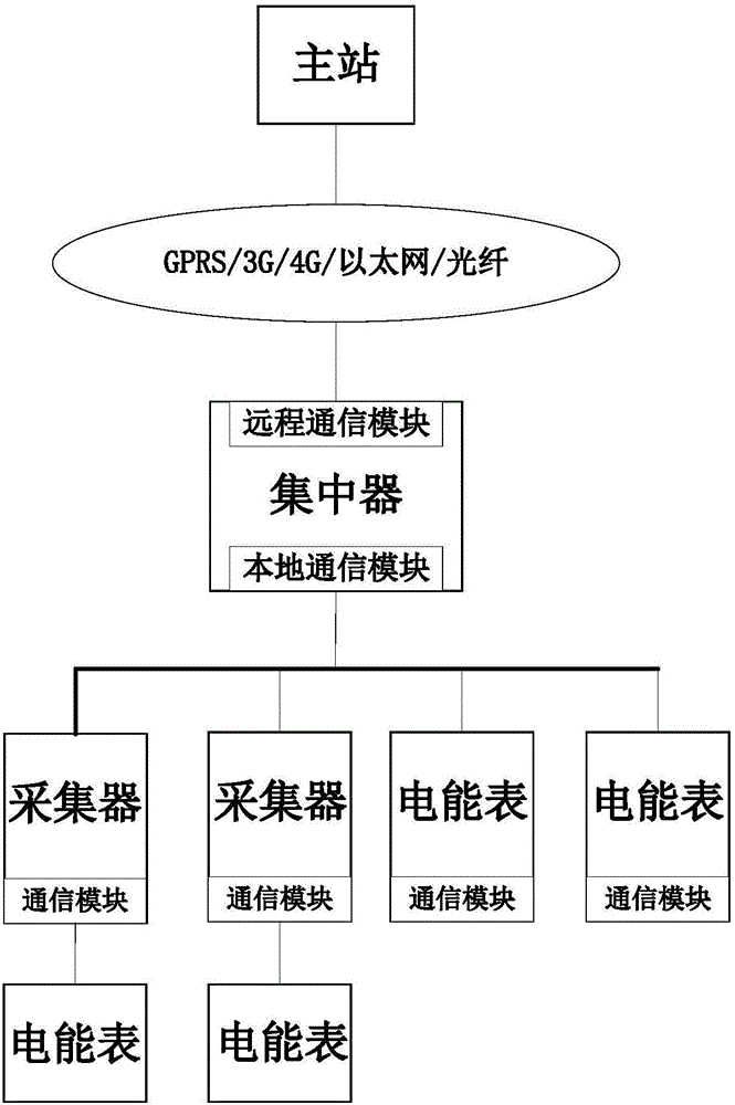
[0020] The embodiments of the present invention will be described in detail below with reference to the accompanying drawings, but the present invention can be implemented in many different ways defined and covered by the claims.

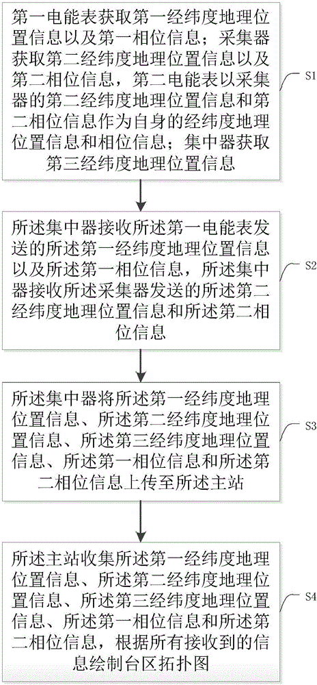
[0021] see figure 1 , a method for automatically obtaining the topological map of the station area of ​​the present invention, comprising the following steps:

[0022] S1: The first electric energy meter obtains the first longitude and latitude geographic location information and the first phase information; The two-phase information is used as its own longitude and latitude geographic location information and phase information; the concentrator obtains the third longitude and latitude geographic location information;

[0023] S2: The concentrator receives the first longitude and latitude geographic location information and the first phase information sent by the first electric energy meter, and the concentrator receives the second longitude and la...


PUM


Abstract

The invention discloses a method and system automatically obtaining a transformer area topological graph, no artificial work is needed, thus reducing errors and omissions caused by artificial drafting; the method comprises the following steps: using a first electric energy meter to obtain first latitude and longitude geography position information and first phase information; using a collector to obtain second latitude and longitude geography position information and second phase information; using the latitude and longitude geography position information and phase information of the collector to serve as that of the second electric energy meter; using a concentrator to obtain third latitude and longitude geography position information; using the concentrator to receive the first latitude and longitude geography position information and the first phase information sent by the first electric energy meter, and the second latitude and longitude geography position information and the second phase information sent by the collector; allowing the concentrator to upload all latitude and longitude geography position information and phase information to a main station; allowing the main station to collect all latitude and longitude geography position information and phase information, and to draft the transformer area topological graph according to all latitude and longitude geography position information and phase information.

Description

technical field [0001] The invention relates to a method for obtaining a topological map of a station area, in particular to a method and a system for automatically obtaining a topological map of a station area. Background technique [0002] The topology map of the station area shows the connection relationship and relative position relationship among transformers, concentrators, and energy meters in the station area. A detailed and complete topology map of the station area can help power companies quickly locate faulty equipment and quickly go to the fault location for maintenance equipment , to restore power to the user. A detailed and complete topological map of the station area can also help improve the collection success rate of the power consumption information collection system. When the collection success rate is not ideal, you can choose the best location to add communication repeaters according to the topological structure of the station area, or move The concentr...

Claims


Application Information

Patent Timeline
Patent Type & Authority Applications(China)
IPC IPC(8): G01S19/42
CPCG01S19/42
Inventor 谭湘平吴志永
Owner 湖南华烨智能通信技术股份有限公司
Why Eureka
Eureka Blog
Learn More