A combined fixture for finishing large-diameter steam trap
A technology of combining fixtures and steam traps, used in manufacturing tools, workpiece clamping devices, etc., can solve problems such as time-consuming, and achieve the effect of facilitating calibration and positioning
- Summary
- Abstract
- Description
- Claims
- Application Information
AI Technical Summary
Problems solved by technology
Method used
Image


Examples
Embodiment 1
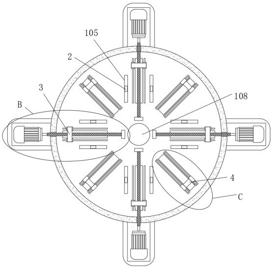
[0028] see figure 1 , figure 2 , image 3 , Figure 4 and Figure 5, the combination fixture for the finishing of large-diameter steam traps of the present invention includes a rotating frame 101, an adjustment assembly 2, a first clamping assembly 3, a second clamping assembly 4 and a drive assembly 5, and the top of the rotating frame 101 is installed with the top The center is provided with some first movable holes 103 and second movable holes 104 for the circular array in the center of the circle, and the top of the installation rotating frame 101 is also provided with some storage grooves 102, and the bottom center of the storage groove 102 is provided with a sliding hole 105, and the rotating frame 101 is installed. The bottom of the inner wall is vertically fixedly connected with a support plate 106 compatible with the sliding hole 105, and the end of the support plate 106 away from the rotating frame 101 is fixedly connected with a rotating plate 107. Slide rail 2...
Embodiment 2
[0031] see figure 1 , figure 2 , Figure 6 and Figure 8 , the first clamping assembly 3 includes a first clamping block 307, the bottom of the first clamping block 307 is fixedly connected with a first movable block 304, a threaded hole 306 is provided in the center of the side of the first movable block 304, and the inner wall of the threaded hole 306 A screw 302 is threadedly connected, and the screw 302 and the first movable block 304 form a ball screw 302;
[0032] The number of the first movable hole 103 and the second movable hole 104 is four, the angle between the four first movable holes 103 is 90 degrees, and the four second movable holes 104 are respectively located in the adjacent first movable holes On the axis of symmetry between 103, install rotating frame 101 to be all fixedly connected limit slide rail 305 near the bottom of first movable hole 103, and the top of limit slide rail 305 is slidingly connected limit slide block 303, and limit slide block The ...
Embodiment 3
[0035] see figure 1 , figure 2 , image 3 , Figure 7 and Figure 9 , the second clamping assembly 4 includes a second clamping block 404 and a second electromagnetic slide rail 401, the bottom of the second clamping block 404 is fixedly connected with the second movable block 402, and the bottom of the second movable block 402 is fixedly connected with the first The second electromagnetic slider 403 that is compatible with the two electromagnetic slide rails 401, the number of the second electromagnetic slide rails 401 is eight, and the two second electromagnetic slide rails 401 form a group, and each group has two second electromagnetic slide rails The rails 401 are respectively distributed on the top of the inner wall of the rotating frame 101 with the axis of the second movable hole 104 as the axis of symmetry. The second electric telescopic rod 406 plays the role of further clamping the trap.
[0036] In the present invention, when the port of the steam trap needs t...
PUM
 Abstract
Description
Claims
Application Information
 - R&D
- Intellectual Property
- Life Sciences
- Materials
- Tech Scout
- Unparalleled Data Quality
- Higher Quality Content
- 60% Fewer Hallucinations
Browse by: Latest US Patents, China's latest patents, Technical Efficacy Thesaurus, Application Domain, Technology Topic, Popular Technical Reports.
© 2025 PatSnap. All rights reserved.Legal|Privacy policy|Modern Slavery Act Transparency Statement|Sitemap|About US| Contact US: help@patsnap.com