
Interferometer device and method for producing an interferometer device

A technology of interferometer and filter device, which can be used in interferometric spectroscopy, measurement devices, instruments, etc., and can solve problems such as reducing the robustness of spectrometers.

Pending Publication Date: 2021-12-21
ROBERT BOSCH GMBH
View PDF1 Cites 0 Cited by
  • Summary
  • Abstract
  • Description
  • Claims
  • Application Information

AI Technical Summary

Problems solved by technology

However, in the case of low pressures, tensile forces are triggered on the adhesive connection and thus reduce the robustness of the spectrometer

Method used


Image

  • Interferometer device and method for producing an interferometer device
  • Interferometer device and method for producing an interferometer device

Examples


Embodiment Construction

[0035] In the figures, identical reference numbers designate identical or functionally identical elements.

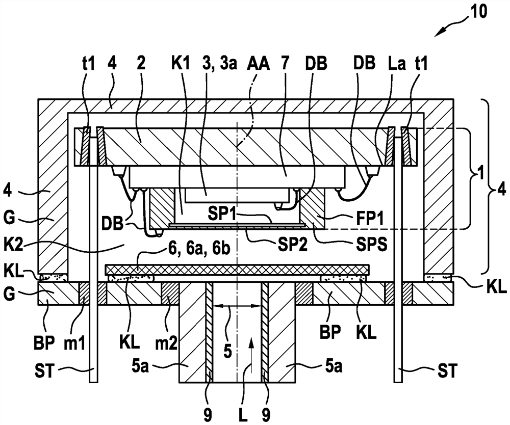
[0036] figure 1 A schematic side view of an interferometer arrangement according to an exemplary embodiment of the invention is shown.

[0037]The interferometer device 10 comprises an interferometer unit 1 with: a base substrate 2 comprising electrical conductor connections La; a Fabry-Perot-unit FPI, the Fabry-Perot - the cells are arranged on the base substrate 2 and form a first cavity K1 in the region of the base substrate 2 and are connected to the electrical conductor connection La; and a detector device 3 , which It is arranged on the base substrate 2 and in the first cavity K1 between the base substrate 2 and the interferometer unit 1 and is connected to the electrical conductor connection La. Furthermore, the interferometer device 10 comprises a housing G which comprises a base plate BP and a cover structure 4 , wherein the cover structure 4 is arranged on t...


PUM


Abstract

The present invention relates to an interferometer device (10), comprising: an interferometer unit (1), which has a base substrate (2), a Fabry-Perot unit (FPI) and a detector device (3); and a housing (G), which comprises a bottom plate (BP) and a cover structure (4), wherein: the cover structure (4) is arranged on the bottom plate (BP) and encloses a second cavity (K2) between the cover structure (4) and the bottom plate (BP); the bottom plate (BP) or the cover structure (4) comprises an opening (5), which is surrounded by side walls (5a), which extend perpendicularly to a surface of the bottom plate (BP) or the cover structure (4); and the interferometer unit (1) is arranged in the second cavity (K2) and in a light incidence direction (L) through the opening (5) such that the Fabry-Perot unit (FPI) of the interferometer unit (1) faces the opening (5).

Description

technical field [0001] The invention relates to an interferometer device and a method for producing the interferometer device. Background technique [0002] A miniaturized spectrometer with a Fabry-Perot interferometer (FPI) can be produced as a compact component and includes a housing with an optical window, the filter usually being able to be fixed on the inside with an adhesive. A low pressure or even a vacuum can exist in the interior of the housing and form a defined atmospheric pressure so that as little as possible gas damping occurs during operation and the mirror spacing in the FPI can be changed rapidly (in the case of the transmitted or filtered tuning within the range of wavelengths of light) in order to obtain short measurement times. However, in the case of low pressures, tensile forces on the adhesive connection can be triggered and the robustness of the spectrometer can thus be reduced. [0003] In WO 17057372 a detector structure for a miniaturized spectro...

Claims


Application Information

Patent Timeline
IPC IPC(8): G01J3/45G01J3/02G02F1/21
CPCG01J3/45G01J3/0205G02F1/21G01J3/0291G01J3/26G01J3/0289G01J3/0262G01J2003/1213
Inventor C·谢林S·克尼斯
Owner ROBERT BOSCH GMBH
Learn More