
V-shaped drag positioning mechanism, material roll feeding device and material roll feeding positioning measurement method

A positioning mechanism and material roll technology, applied in the direction of measuring device, force/torque/work measuring instrument, winding strip, etc., can solve the problem of inaccurate positioning of AGV trolley, achieve convenient feeding, ensure concentricity, The effect of preventing safety hazards

Inactive Publication Date: 2021-12-21
常州恒锌禹晟智能装备股份有限公司
View PDF10 Cites 0 Cited by
  • Summary
  • Abstract
  • Description
  • Claims
  • Application Information

AI Technical Summary

Problems solved by technology

[0003] The purpose of the present invention is to provide a V-shaped dragging positioning mechanism, a material coil feeding device and a material coil feeding positioning measurement method, to solve the problem that the feeding device of the coating machine in the past does not have a corresponding positioning mechanism to assist, and the AGV trolley is in the process of conveying Technical problem of inaccurate positioning when feeding rolls

Method used


Image

  • V-shaped drag positioning mechanism, material roll feeding device and material roll feeding positioning measurement method
  • V-shaped drag positioning mechanism, material roll feeding device and material roll feeding positioning measurement method
  • V-shaped drag positioning mechanism, material roll feeding device and material roll feeding positioning measurement method

Examples


Embodiment 1

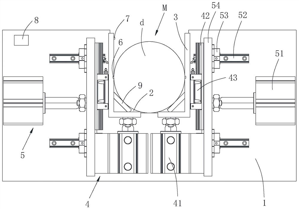
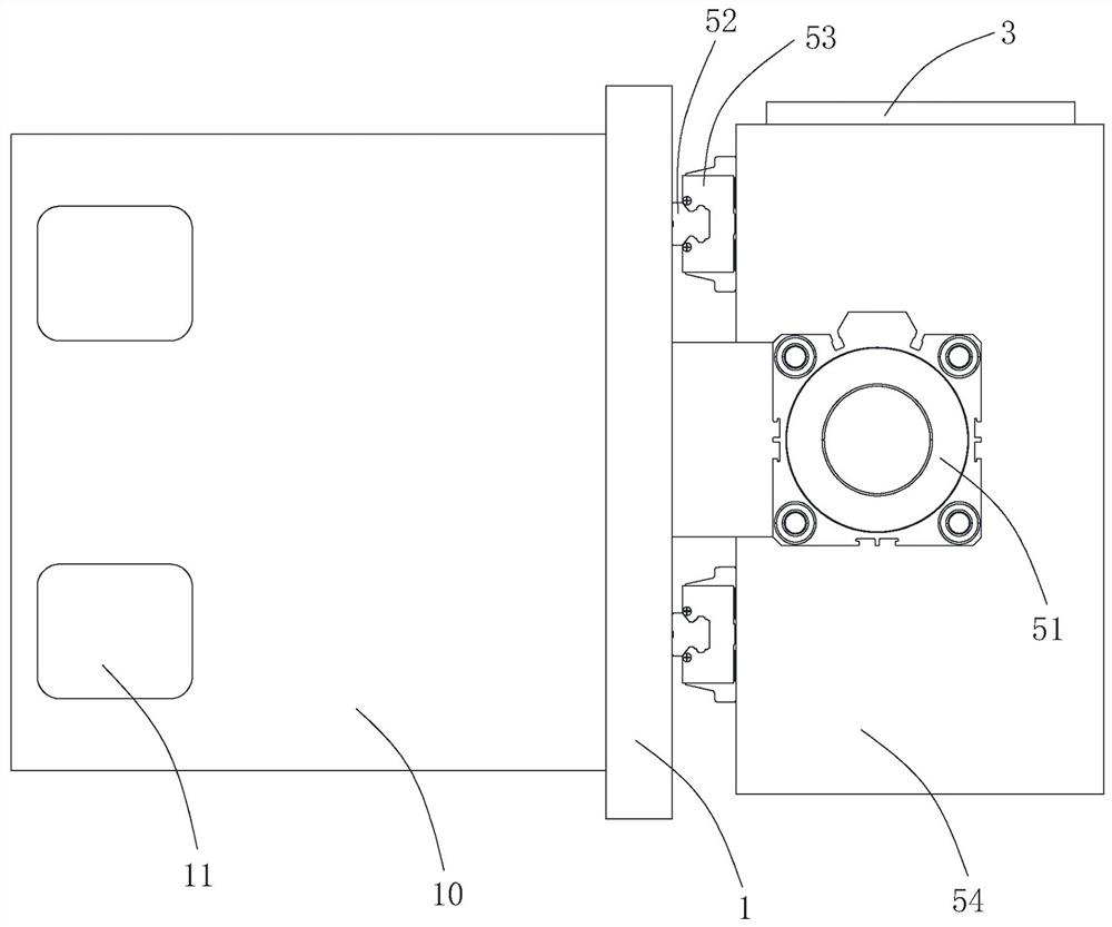
[0062] Such as figure 1 As shown, the V-shaped drag positioning mechanism of the present embodiment includes: a V-shaped drag plate 1 fixedly arranged, the top of the V-shaped drag plate 1 is provided with a V-shaped groove 2 for pre-carrying a roll d; The L-shaped clamps 3 on both sides of the groove 2, and the two L-shaped clamps 3 can perform lifting and translation movements on the V-shaped pallet 1; Position M, so that the coil d is coaxial with the inflatable shaft; the height of the L-shaped clamp dragging 3 moving up is ;

[0063] Among them, △H is the height difference before and after the lifting of the L-shaped clamp 3;

[0064] H is the vertical height between the L-shaped clip 3 and the axis of the air expansion shaft before lifting, which is a known constant;

[0065] D is the distance between the vertical sections of the two L-shaped clips 3, which is a measured value. Because the two L-shaped clips 3 are clamped on both sides of the material roll d, the dista...

Embodiment 2

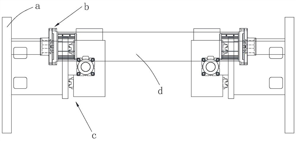
[0078] like Figure 1 to Figure 3 As shown, on the basis of Example 1, this Example 2 provides a lithium battery pole piece coil feeding device, including: a pair of support columns a, a pair of inflatable shaft mechanisms b, and a pair of V Type drag positioning mechanism c; wherein, the inflatable shaft mechanism b is arranged on the corresponding support column a, and the inflatable shaft mechanism b can extend laterally to the loading station M so that the inflatable shaft can expand and tighten the positioning material roll d; V The type drag positioning mechanism c is set on the corresponding support column a; the two translation components 5 on the same side translate the corresponding end of the clamping material roll d in opposite directions, and the corresponding lifting component 4 moves up synchronously to push the corresponding L-shaped clamp drag 3 supports The material roll d is moved up to the feeding station M, so that the material roll d in the V-shaped groov...

Embodiment 3

[0080] like Figure 1 to Figure 3 As shown, on the basis of Embodiment 2, this Embodiment 3 provides a positioning measurement method for material roll loading, including: two translation components 5 respectively push the corresponding lifting component 4 to translate to the V-shaped groove 2, so as to push the two L-shaped The gripper 3 translates the clamped material roll d in opposite directions; the pressure sensor 6 embedded in the L-shaped gripper 3 is pressed and triggered to send a signal to the controller 8, and the controller 8 controls the translation component 5 to stop translation; the distance sensor 7 measures the two L-shaped The spacing D of the vertical section of the clamping drag 3 is used to measure the actual diameter of the end of the material roll d; the controller 8 receives the data of the measured value D of the spacing and calculates , so as to control the lifting component 4 to drive the L-shaped clamp 3 to move up to a height of △H, so that the ...


PUM


Abstract

The invention belongs to the technical field of positioning devices, and particularly relates to a V-shaped drag positioning mechanism, a material roll feeding device and a material roll feeding positioning measurement method. The V-shaped drag positioning mechanism comprises a V-shaped drag plate, and a V-shaped groove is formed in the top of the V-shaped drag plate; L-shaped clamping supports are arranged on the two sides of the V-shaped groove, and the L-shaped clamping supports can ascend, descend and move horizontally; the two L-shaped clamping supports horizontally move in opposite directions to clamp and lift a material coil to a feeding station, so that the material coil and an air swelling shaft are coaxial; and the upward moving height of the L-shaped clamping supports is equal. According to the V-shaped drag positioning mechanism, the material coil feeding device and the material coil feeding positioning measurement method, the two L-shaped clamping supports oppositely translate to clamp the material coil and lift the material coil to the feeding station, the upward movement height of the L-shaped clamping supports is calculated through a formula, delta H is determined according to the measured value of the distance between the vertical sections of the two L-shaped clamping supports, it is guaranteed that the material coil can be precisely lifted to the feeding station, precise positioning is achieved, it is effectively ensured that the material coil and the air swelling shaft are coaxial, and follow-up feeding is facilitated. The material coil is prevented from falling off and hurting people when being positioned with the air swelling shaft, and potential safety hazards are prevented.

Description

technical field [0001] The invention belongs to the technical field of positioning devices, and in particular relates to a V-shaped drag positioning mechanism, a material coil feeding device and a material coil feeding positioning measurement method. Background technique [0002] In the production process of lithium battery diaphragm coating, it is generally necessary to put the material roll into the feeding station of the coating machine, so as to facilitate the subsequent loading and unloading of the feeding device. The existing technology is to rely on the AGV trolley to transport the material roll to the loading station, which is convenient and quick to operate and has a high degree of automation. However, the feeding device does not have a corresponding positioning mechanism to assist, and the AGV trolley may be inaccurately positioned when conveying the material roll, and the material roll cannot be coaxial with the inflatable shaft, which will affect the subsequent f...

Claims


Application Information

Patent Timeline
Patent Type & Authority Applications(China)
IPC IPC(8): B65H19/12G01L5/00G01B21/16
CPCB65H19/126G01L5/00G01B21/16
Inventor 舒星火陈禹孙兆安丁晓峰
Owner 常州恒锌禹晟智能装备股份有限公司
Learn More