Rapid feeding device and feeding method for injection molding equipment

A technology of injection molding equipment and material suction device, which is applied in the field of rapid feeding device of injection molding equipment, can solve the problems of high labor intensity, small packaging capacity, waste of site area, etc., so as to improve the qualified rate of products, reduce the number of feeding times, and reduce inventory. area effect

Pending Publication Date: 2021-12-21
DONGFENG VISTEON AUTOMOTIVE TRIM SYST CO LTD
View PDF4 Cites 0 Cited by
  • Summary
  • Abstract
  • Description
  • Claims
  • Application Information

AI Technical Summary

Problems solved by technology

[0002] The existing injection molding equipment is loaded with small tape packaging (25KG), resulting in waste of site area, repeated handling by employees, high labor intensity and potential safety hazards, etc.
The corresponding feeding method has the following disadvantages: 1. Due to the small capacity of a single package, it occupies a large area; 2. The labor intensity of the personnel is high when the material is transported and loaded multiple times, and there is a safety accident when the bag is cut with a knife; 3. When loading materials in small packages, operators tend to forget to load materials, and wait until the product has a material shortage alarm before reloading materials, which results in a low product qualification rate

Method used


Image

  • Rapid feeding device and feeding method for injection molding equipment
  • Rapid feeding device and feeding method for injection molding equipment
  • Rapid feeding device and feeding method for injection molding equipment

Examples


Embodiment Construction

[0022] The present invention will be further described in detail below in conjunction with the accompanying drawings and specific embodiments to facilitate a clear understanding of the present invention, but they do not limit the present invention.

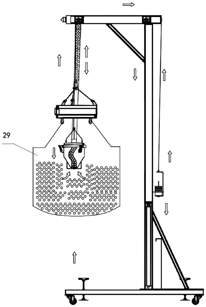
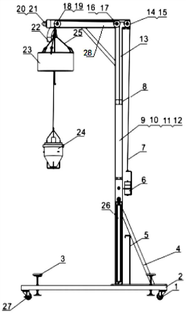
[0023] Such as Figure 1-2 As shown, a fast feeding device for injection molding equipment of the present invention includes a bracket, and one end of the top of the bracket is provided with a first pulley 14, a first wire baffle 15, a second pulley 16, a second wire baffle 17, and the other end Set the third pulley 18, one end of the first steel wire rope 7 is connected with the weight set 6, and the other end is passed through the first pulley 14 and the third pulley 18 in turn, and passes through the suspension ring 23 and is connected with the suction device 24 , the bottom of the suction device 24 is provided with a feed port for sucking the material in the ton bag 29, and the top of the suction device 24 is connected to the ...


PUM


Abstract

The invention discloses a rapid feeding device and feeding method for injection molding equipment. The device comprises a support, a first belt wheel and a second belt wheel are arranged at one end of the top of the support, a third belt wheel is arranged at the other end of the top of the support, one end of a first steel wire rope is connected with a weight set, the other end of the first steel wire rope sequentially penetrates through the first belt wheel and the third belt wheel, penetrates through a hanging ring and is connected with a material suction device, a material inlet is formed in the bottom of the material suction device, the top of the material suction device is connected with a material suction machine through a material suction pipe, one end of the second steel wire rope is connected with the output end of the air cylinder, and the other end of the second steel wire rope sequentially penetrates through the second belt wheel and the third belt wheel and is connected with the hanging ring. The packaging amount is improved, automatic feeding is achieved, the labor intensity of workers can be reduced, the feeding working hours are saved, and the problems of product breakage and shortage are solved.

Description

technical field [0001] The invention belongs to the technical field of injection molding equipment feeding, and in particular relates to a fast feeding device and a feeding method for injection molding equipment. Background technique [0002] The existing injection molding equipment uses small tape packaging (25KG) for loading materials, resulting in waste of site area, repeated handling by employees, high labor intensity and potential safety hazards. The corresponding feeding method has the following disadvantages: 1. Due to the small capacity of a single package, it occupies a large area; 2. The labor intensity of the personnel is high when the material is transported and loaded multiple times, and there is a safety accident when the bag is cut with a knife; 3. When loading materials in small packages, operators tend to forget to load materials, and wait until the product has a material shortage alarm before re-loading, which results in a low product qualification rate. ...

Claims


Application Information

Patent Timeline
Patent Type & Authority Applications(China)
IPC IPC(8): B29C45/18B29C31/04
CPCB29C45/18B29C31/04
Inventor 蔡镇周周全安韩小亮
Owner DONGFENG VISTEON AUTOMOTIVE TRIM SYST CO LTD
Why Eureka
Try Eureka