Automatic binding and welding equipment for steel bars of highway T-beam wing plate and using method of automatic binding and welding equipment

A beam and wing plate and equipment technology is applied in the field of automatic binding and welding equipment for the reinforcement of the T beam and wing plate of the highway, which can solve the problems of low processing and installation efficiency of the steel bar of the T beam and wing plate, time-consuming and laborious, etc., so as to improve the binding and welding efficiency and release the manual labor. , the effect of improving quality

Pending Publication Date: 2021-12-21
中国建筑土木建设有限公司
View PDF4 Cites 0 Cited by
  • Summary
  • Abstract
  • Description
  • Claims
  • Application Information

AI Technical Summary

Problems solved by technology

[0004] The invention provides an automatic binding and welding equipment for highway T-beam wing plate reinforcement and its use method, which is used to solve the technical problems that the current traditional operation method is time-consuming and labor-intensive, and the processing and installation efficiency of T-beam wing plate reinforcement is very low

Method used


Image

  • Automatic binding and welding equipment for steel bars of highway T-beam wing plate and using method of automatic binding and welding equipment
  • Automatic binding and welding equipment for steel bars of highway T-beam wing plate and using method of automatic binding and welding equipment
  • Automatic binding and welding equipment for steel bars of highway T-beam wing plate and using method of automatic binding and welding equipment

Examples


Embodiment Construction

[0038] The technical solutions of the present invention are described in detail below through the examples, and the following examples are only exemplary, and can only be used to explain and illustrate the technical solutions of the present invention, but cannot be construed as limitations to the technical solutions of the present invention.

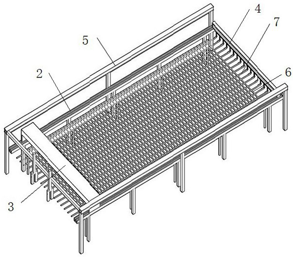
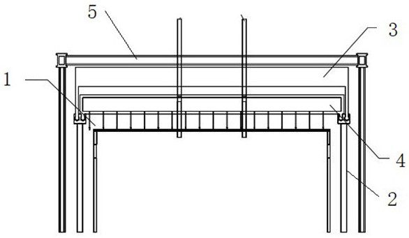
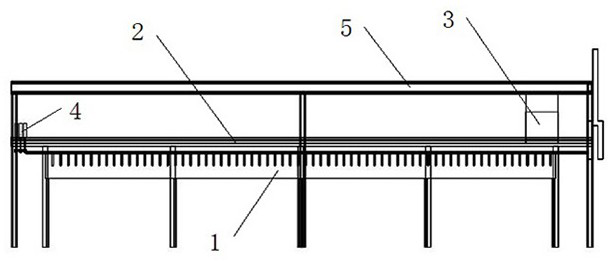
[0039] combine Figure 1-3 , an automatic binding and welding equipment for highway T-beam wing plate reinforcement, comprising,

[0040] The tire frame 1 is provided with a groove for placing the transverse steel bar 6 for positioning the transverse steel bar 6;

[0041] The equipment outer frame and guide rail 2 are set on the outer side of the tire frame 1, and both ends exceed the tire frame 1. The end beyond the tire frame 1 is equipped with an automatic welding device 3, and the other end beyond the tire frame 1 is installed with a longitudinal beam positioner 4;

[0042] The automatic binding and welding equipment 3 is slidably ...


PUM


Abstract

The invention discloses automatic binding and welding equipment for steel bars of a highway T-beam wing plate. The automatic binding and welding equipment comprises a jig frame, an equipment outer frame, a guide rail, automatic binding and welding equipment, a longitudinal beam positioner, an AGV carrying robot, a truss robot guide rail and an intelligent control cabinet. A truss robot can be automatically controlled, so that part of personnel can be reduced, and the efficiency can be improved; in addition, a PLC line at the bottom of the intelligent control cabinet is connected with a PLC interface of the automatic binding and welding equipment, and automatic binding and welding are set according to the distance between a longitudinal beam and a transverse beam in the mounting process, so that the binding and welding efficiency is improved, and personnel requirements are reduced; and furthermore, the longitudinal beam positioner is further researched and developed, so that the problem of poor position placement accuracy of longitudinal steel bars can be avoided. Therefore, the equipment not only improves the efficiency of binding and welding the steel bars of the highway T-beam wing plate, but also greatly reduces the requirements on personnel, reduces the needs of the personnel, and improves the quality of finished products.

Description

technical field [0001] The invention belongs to the technical field of road construction, and in particular relates to an automatic binding and welding device for reinforcing bars of a T-beam wing plate of a road and a using method thereof. Background technique [0002] The wing plate reinforcement is the basic skeleton of the highway T-beam. It is mainly composed of main reinforcement, longitudinal reinforcement and other connections, positioning reinforcement and other metal components that are fixed and bound or welded. It is a prestressed reinforced concrete structure commonly used in modern bridges. [0003] At present, during the processing and installation of prefabricated T-beam flange reinforcement, workers bind the flange reinforcement on the tire frame by hand. The work efficiency is low, and some small module reinforcement bars need to be welded on site, posing health risks. Not only that, the retrieving and positioning of semi-finished products also rely on manu...

Claims


Application Information

Patent Timeline
Patent Type & Authority Applications(China)
IPC IPC(8): B23K31/02B23K37/00B23K37/04E04G21/12
CPCE04G21/122B23K31/02B23K37/00B23K37/0435
Inventor 于鑫李京跃敖长江宋合财郜卫东朱建平
Owner 中国建筑土木建设有限公司
Why Eureka
Try Eureka