Eureka AIR delivers breakthrough ideas for toughest innovation challenges, trusted by R&D personnel around the world.

Vertical double-workpiece multi-head slot milling machine

A double-workpiece and slot milling machine technology, which is applied to metal processing machinery parts, milling machine equipment, manufacturing tools, etc., can solve the problems of inconvenient multi-workpiece clamping, redundant milling cutter power devices, and flying aluminum chips.

Pending Publication Date: 2021-12-21
佛山市银弧机电设备有限公司
View PDF0 Cites 2 Cited by
  • Summary
  • Abstract
  • Description
  • Claims
  • Application Information

AI Technical Summary

Problems solved by technology

This type of aluminum formwork milling machine has the following disadvantages: the hanging clamping is not convenient for multi-workpiece clamping, and the processing efficiency is low; the hanging clamping can only process and mill the aluminum formwork profiles before welding; one side of the aluminum formwork is processed Finally, because the grooves are milled at unequal intervals on both symmetrical sides of the aluminum formwork, when the other side needs to be processed, it is necessary to turn the aluminum formwork upside down and at the same time, turn it over 180° along the length direction, and then clamp and fix it, so it is necessary The number of slots on one side plus two The milling cutter power unit can complete the milling of the number of grooves with unequal spacing on both sides of the symmetrical aluminum template. The milling cutter power unit is redundant and labor-intensive. At the same time, the tool mills grooves on the workpiece, causing aluminum chips to fly randomly, which is inconvenient. Collected, and the tool is exposed, accidents are prone to occur when clamping the workpiece, and there are potential safety hazards

Method used


Image

  • Vertical double-workpiece multi-head slot milling machine
  • Vertical double-workpiece multi-head slot milling machine
  • Vertical double-workpiece multi-head slot milling machine

Examples


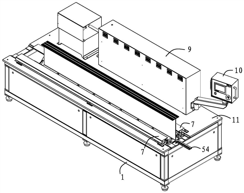
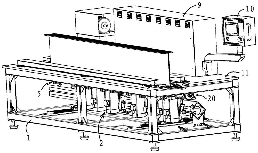
Embodiment Construction

[0027] The present invention will be described in further detail below in conjunction with the accompanying drawings.

[0028] refer to Figure 1 to Figure 9 : Vertical double-workpiece multi-head milling machine, including frame 1, milling cutter power device 2, front and rear drive device 3, up and down drive device 4 and pneumatic clamping device 5, frame 1 is provided with workbench 11, milling cutter The power unit 2 is located below the workbench 11 with the milling cutter facing upwards. The front and rear driving devices 3 are arranged on the frame 1 and connected with the moving beam 35, the up and down driving devices 4 are connected with the milling cutter power device 2, the pneumatic clamping device 5 is arranged on the workbench 11, and the pneumatic clamping device 5 and the milling cutter The power unit 2 is matched accordingly.

[0029] When the vertical double-workpiece multi-head milling machine is in use, the two aluminum templates to be processed are pla...


PUM


Abstract

The invention discloses a vertical double-workpiece multi-head slot milling machine. The vertical double-workpiece multi-head slot milling machine is suitable for the building aluminum template manufacturing industry. The vertical double-workpiece multi-head slot milling machine is special equipment for groove milling of aluminum templates of a pull tab system. The vertical double-workpiece multi-head slot milling machine comprises a machine frame, milling cutter power devices, a front-back driving device, an up-down driving device and a pneumatic clamping device, wherein a workbench is arranged on the machine frame, the milling cutter power devices are arranged below the workbench and workpieces, suspensions of the milling cutter power devices and the front-back driving device are arranged on the machine frame, and the up-down driving device is connected with the milling cutter power devices; and the pneumatic clamping device is arranged on the workbench and located below the workpieces, and the pneumatic clamping device is correspondingly matched with the milling cutter power devices. The workpieces are placed on the pneumatic clamping device, the workpieces can be clamped and fixed by taking a machining surface as a reference, the workpieces can be conveniently and quickly fixed, and the machining surfaces of the workpieces face downwards; and the workpieces are positioned above milling cutters. When the other faces of the workpieces are machined, only the workpieces need to be overturned up and down, clamping is convenient, the workload is reduced, and the machining efficiency is improved.

Description

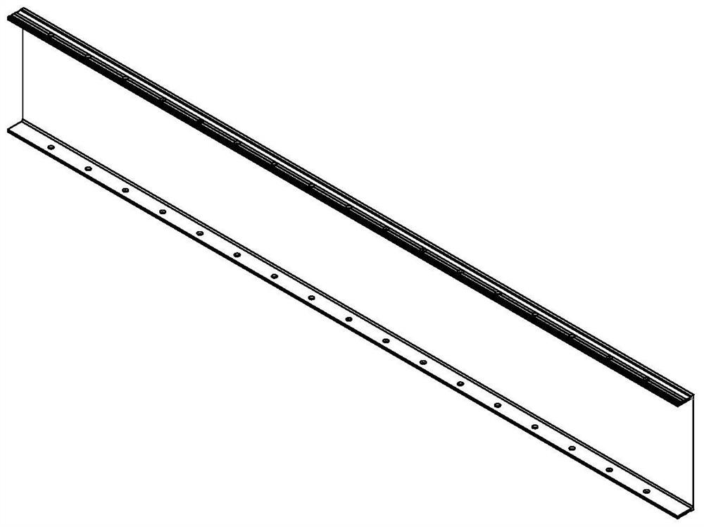
technical field [0001] The invention belongs to a groove milling machine for building aluminum templates, in particular to a vertical double-workpiece multi-head groove milling machine. Background technique [0002] Architectural aluminum formwork, such as: the standard wallboard with a U-shaped cross section of the pull tab system, when milling grooves, due to the existing special equipment for aluminum formwork milling grooves, when milling grooves on aluminum formwork, the workpiece adopts hanging clamps Tight, the tool mills a slot above the workpiece. This type of aluminum formwork milling machine has the following disadvantages: the hanging clamping is not convenient for multi-workpiece clamping, and the processing efficiency is low; the hanging clamping can only process and mill the aluminum formwork profiles before welding; one side of the aluminum formwork is processed Finally, because the grooves are milled at unequal intervals on both symmetrical sides of the alu...

Claims


Application Information

Patent Timeline
Patent Type & Authority Applications(China)
IPC IPC(8): B23C3/28B23Q3/08B23Q1/25B23Q5/34B23Q11/08
CPCB23C3/28B23Q3/062B23Q3/08B23Q1/25B23Q5/34B23Q11/08B23Q2703/04
Inventor 罗良栋
Owner 佛山市银弧机电设备有限公司
Why Eureka
Eureka Blog
Learn More