
Drilling device for machining of numerical control machine tool

A technology of CNC machine tools and drilling equipment, which is applied in metal processing equipment, drilling/drilling equipment, metal processing, etc., can solve the problems of prolonged drilling processing time, poor workpiece quality, and reduced processing efficiency, and achieve saving Reduce clamping time, improve drilling efficiency, and improve accuracy

Active Publication Date: 2021-12-21
XIANYANG ZHONGBING ELECTROMECHANICAL EQUIP MFG
View PDF10 Cites 0 Cited by
  • Summary
  • Abstract
  • Description
  • Claims
  • Application Information

AI Technical Summary

Problems solved by technology

[0003] Before drilling the workpiece with the existing drilling equipment for CNC machine tool processing, the material needs to be clamped on the machine tool first, and then positioned, and the drilling can only start after positioning. A CNC machine tool with the application number CN202020196686.7 Drilling equipment for processing uses this method to fix the material to prevent the material from shifting during the drilling process. However, this process is relatively cumbersome, and the handle needs to be manually loosened when clamping, and then manually tightened when clamping. As a result, the clamping time of the workpiece is prolonged, which eventually leads to the prolongation of the actual drilling time, which is not conducive to the rapid operation of workers and reduces the processing efficiency. The efficiency of hole processing is high, but there is no effective fixation during the drilling process, which will easily cause the material to shake and the drilling position to shift, which will eventually lead to poor quality of the workpiece and affect subsequent use

Method used


Image

  • Drilling device for machining of numerical control machine tool
  • Drilling device for machining of numerical control machine tool
  • Drilling device for machining of numerical control machine tool

Examples


Embodiment Construction

[0033] In order to describe the technical solution of the present invention more clearly and completely, the present invention will be further described below in conjunction with the accompanying drawings.

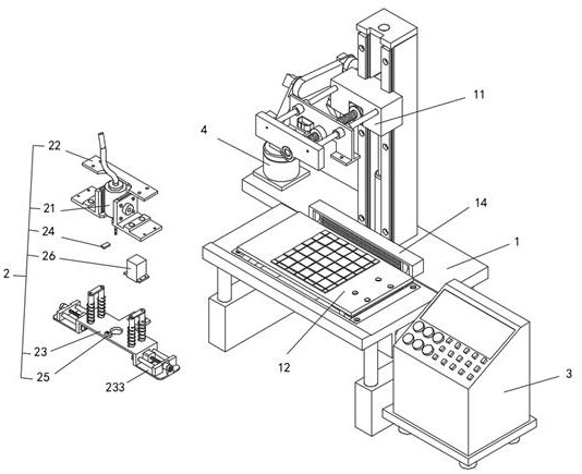
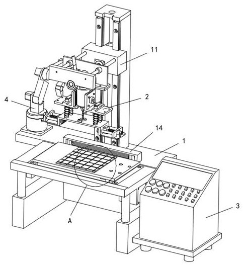
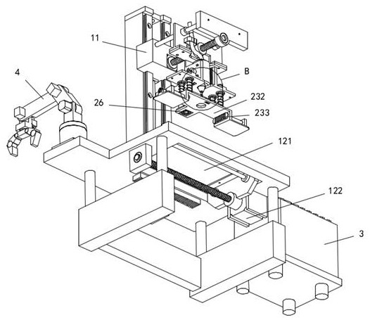
[0034] Please refer to Figure 1-Figure 10 , the present invention proposes a drilling device for CNC machine tool processing, including a bed body 1, a drilling device 2 and a console 3, the console 3 is located on one side of the bed body 1 and is electrically connected to the bed body 1 and the drilling device 2 respectively The drilling device 2 is suspended and fixed on the boom 11 of the bed body 1, the drilling device 2 includes a drill bit 21, a fixed frame 22, a telescopic assembly 23, a first distance sensor 24, a second distance sensor 25, and an image acquisition device 26, The fixed frame 22 is fixedly connected to the boom 11, the drill bit 21 is fixedly connected to the fixed frame 22 and protrudes from the fixed frame 22 toward the bed body 1, and the teles...


PUM


Abstract

The invention provides a drilling device for machining of a numerical control machine tool. The drilling device comprises a machine tool body, a drilling apparatus and a console, the console is located at one side of the machine tool body and electrically connected with the machine tool body and the drilling apparatus, the drilling apparatus is suspended and fixed to a suspension arm of the machine tool body, and the drilling apparatus comprises a drill bit, a fixing frame, a telescopic assembly, a first distance sensor, a second distance sensor and an image acquisition device. According to the drilling device for machining of the numerical control machine too, the upper end surface of a workpiece is pressed and clamped by the telescopic assembly before drilling, a clamping device is adopted for auxiliary clamping in the clamping process of the telescopic assembly, the image acquisition device is adopted for positioning of the workpiece, a mechanical arm is adopted for automatic placement of the workpiece, the accuracy of workpiece drilling is improved, the clamping time for workers is saved, and the drilling machining efficiency of the workpiece is improved.

Description

technical field [0001] The invention relates to the technical field of mechanical processing, in particular to a drilling device for numerically controlled machine tools. Background technique [0002] As we all know, the drilling equipment for CNC machine tool processing is a kind of drilling auxiliary device for CNC machine tool processing, which has been widely used in the field of CNC machine tool processing. [0003] Before drilling the workpiece with the existing drilling equipment for CNC machine tool processing, the material needs to be clamped on the machine tool first, and then positioned, and the drilling can only start after positioning. A CNC machine tool with the application number CN202020196686.7 Drilling equipment for processing uses this method to fix the material to prevent the material from shifting during the drilling process. However, this process is relatively cumbersome, and the handle needs to be manually loosened when clamping, and then manually tigh...

Claims


Application Information

Patent Timeline
IPC IPC(8): B23B47/00B23Q3/06B23Q17/00B23Q7/00B23Q7/04
CPCB23B47/00B23Q3/06B23Q17/006B23Q7/008B23Q7/043
Inventor 刘奇涛淡军平吴强张勇张乐平张辉赵浩王晶李睿远张攀
Owner XIANYANG ZHONGBING ELECTROMECHANICAL EQUIP MFG
Learn More