


Quick Research
Generate reliable direction feasibility study reports for your R&D in just a few steps.

Technical Q&A
Discover and master advanced knowledge NOW. Basics, ideas, possibilities, all at once.

Find Solutions
As an expert in R&D theories, this can generate solutions to your technical problems instantly.

Evaluate Feasibility
Analyze your overall solution with one click, know your potential R&D risks in advance.

Monitor Landscape
Get weekly tech updates, stay abreast of the latest tech innovations and key insights.
A wood spraying device
A technology for wood boards and pedals, which is applied in the field of wood board painting devices, can solve the problems of labor consumption, cumbersome operation process, low work efficiency, etc., and achieve the effects of improving work efficiency, simple operation and saving labor.
- Summary
- Abstract
- Description
- Claims
- Application Information
AI Technical Summary
Problems solved by technology
Method used
Image


Examples
Embodiment 1
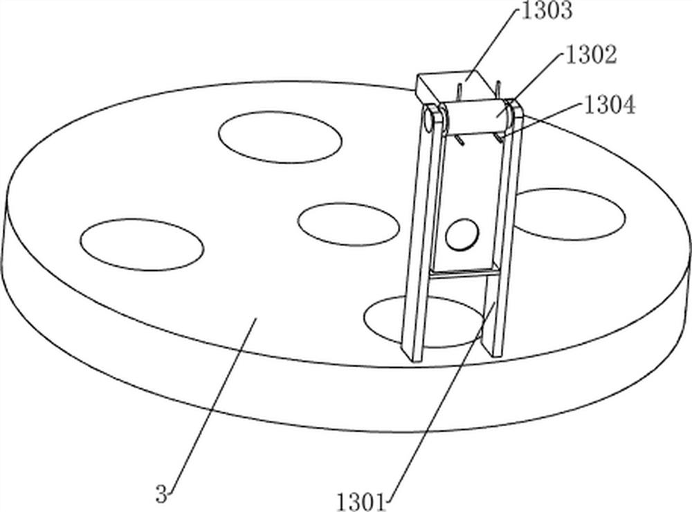
[0034] A wood panel spraying device, such as Figure 1-4 As shown, it includes a first support frame 1, a first support plate 2, a second support frame 3, a charging chute 4, a lowering bucket 5, a pedal 6, a brush frame 7, a clamping mechanism 8 and a first pressing mechanism 9. The top of the first support frame 1 is connected with a first support plate 2, the top of the first support plate 2 is connected with a second support frame 3, and the top of the second support frame 3 is connected with four charging troughs 4 evenly spaced along the circumferential direction, Four unloading buckets 5 are connected to the second support frame 3 , the unloading buckets 5 are matched with the charging chute 4 , the first support frame 1 is slidably connected with a pedal 6 , and the first support plate 2 is rotatably connected with a brush The frame 7, the top of the brush frame 7 is provided with two clamping holes, and the first support plate 2 is provided with a clamping mechanism 8...
Embodiment 2
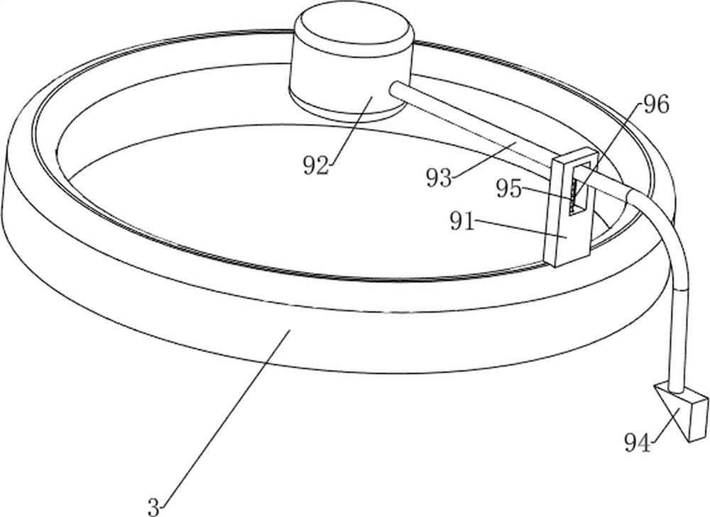
[0040] On the basis of Example 1, as Figure 5 As shown, it also includes a second pressing mechanism 10, the second pressing mechanism 10 includes an annular pressing plate 101, a fourth support rod 103 and a pressing block 102, and an annular pressing plate 101 is connected between the plurality of pressing rods 93. A plurality of fourth support rods 103 are connected to the top of the pressing plate 101 at uniform intervals along the circumferential direction, and pressing blocks 102 are connected between the plurality of fourth support rods 103 .
[0041] When it is necessary to squeeze the lower pressure rod 93 to move downward, the pressure block 102 can be squeezed to move downward, and the downward movement of the pressure block 102 drives the annular pressure plate 101 to move downward through the fourth support rod 103 , and the annular pressure plate 101 moves downward to drive the downward movement. The pressing rod 93 moves downward, thereby driving the pressing r...
Embodiment 3
[0045] On the basis of Example 2, as Figure 7 , Figure 9 , Figure 10 and Figure 11 As shown, it also includes a pressing mechanism 12, and the pressing mechanism 12 includes a sliding frame 1200, a fifth support rod 1201, a second limit rod 1202, a fourth spring 1203, a pressing column 1204, a baffle 1205, and a torsion spring 1206, the pressing frame 1207 and the compression spring 1208, the second support frame 3 is connected with a sliding frame 1200, and the sliding frame 1200 is connected with four sets of second limit rods 1202 at uniform intervals along the circumferential direction, and each set of second limit rods 1202 A fifth support rod 1201 is slidably connected to the upper part, a fourth spring 1203 is connected between the fifth support rod 1201 and the sliding frame 1200, and an extrusion column 1204 is connected to the fifth support rod 1201, and the extrusion column 1204 is connected with the blanking material. The barrel 5 is slidably matched, the bo...
PUM
 Abstract
Description
Claims
Application Information
 - R&D Engineer
- R&D Manager
- IP Professional
- Industry Leading Data Capabilities
- Powerful AI technology
- Patent DNA Extraction
Browse by: Latest US Patents, China's latest patents, Technical Efficacy Thesaurus, Application Domain, Technology Topic, Popular Technical Reports.
© 2024 PatSnap. All rights reserved.Legal|Privacy policy|Modern Slavery Act Transparency Statement|Sitemap|About US| Contact US: help@patsnap.com