Microwave oven with integrated lower surface heating plate

A technology for microwave ovens and heating plates, applied in the field of microwave ovens, can solve the problems of hindering the heating of lower heating elements and the like

Pending Publication Date: 2021-12-17
WHIRLPOOL CORP
View PDF0 Cites 0 Cited by
  • Summary
  • Abstract
  • Description
  • Claims
  • Application Information

AI Technical Summary

Problems solved by technology

However, in order to allow microwaves to penetrate effectively into the cavity, this heating element must be positioned at the rear of the cavity, which prevents the lower heating element from providing beneficial heating to the bottom of the food

Method used


Image

  • Microwave oven with integrated lower surface heating plate
  • Microwave oven with integrated lower surface heating plate
  • Microwave oven with integrated lower surface heating plate

Examples


Embodiment Construction

[0017] The presently shown embodiments consist primarily of a combination of equipment components related to a microwave oven. Thus, where appropriate, apparatus components and method steps have been represented by conventional symbols in the drawings, showing only those specific details that are relevant to an understanding of the embodiments of the disclosure, so as to avoid obscuring the disclosure with details, which Details will be apparent to one of ordinary skill in the art having the benefit of the description herein. In addition, the same reference numerals denote the same elements in the specification and drawings.

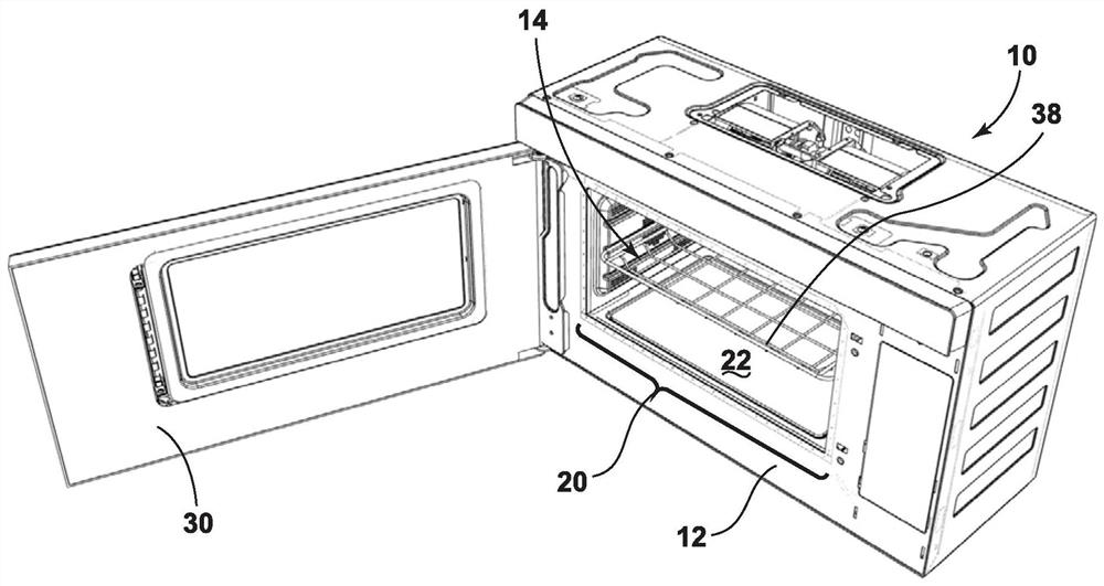
[0018] For the purposes of this description, the terms "upper", "lower", "right", "left", "rear", "front", "vertical", "horizontal" and their derivatives shall be used as such figure 1 This disclosure is oriented in . Unless otherwise stated, the term "front" shall refer to the surface of the element closer to the intended viewer, and the term "rear" s...


PUM


Abstract

A microwave oven comprises: a housing defining an interior cavity; a magnetron positioned within the housing and external to the internal cavity; and a microwave antenna in electrical communication with the magnetron and positioned adjacent to a lower surface of the interior cavity. The microwave oven also includes a heating plate including a glass ceramic substrate defining at least a portion of the lower surface of the interior cavity. The heating plate further includes a resistive heating coating applied on a portion of the glass ceramic substrate, and the heating plate defines at least one unobstructed microwave transmission path from the microwave antenna to the interior cavity.

Description

Background technique [0001] The present disclosure relates generally to a microwave oven and, more particularly, to a microwave oven having a resistive heating plate along a portion of a lower interior cavity surface. [0002] Existing microwave ovens have incorporated an upper heating element (such as a quartz heating tube) with an adjacent reflective area for directing radiant heat from the heating element downwards towards the food in the cavity to provide baked / cooked or crispy cooking mode. However, it is understood that such a solution only radiates heat to one side of the food (ie the upper side), while the other side is only cooked by microwaves. Some other existing solutions add additional heating elements below the lower surface (which can be made of glass). However, in order to allow microwaves to penetrate effectively into the cavity, such heating elements must be positioned at the rear of the cavity, which prevents the lower heating elements from providing benef...

Claims


Application Information

Patent Timeline
Patent Type & Authority Applications(China)
IPC IPC(8): F24C7/02F24C7/06F24C15/02
CPCF24C7/02F24C7/062F24C15/028
Inventor 胡建安吴平厉鑫毛雪婷余婷婷M·希扎尔
Owner WHIRLPOOL CORP
Why Eureka
Try Eureka