Panel system having mounting and hinge assembly with mounting profile and hinge

A technology of hinge components and panels, applied in the direction of roof, roof cladding, construction, etc., to achieve the effect of easy installation

Pending Publication Date: 2021-12-17
VKR HLDG AS
View PDF3 Cites 0 Cited by
  • Summary
  • Abstract
  • Description
  • Claims
  • Application Information

AI Technical Summary

Problems solved by technology

[0004] Although these solutions have proven to work well over the years, there is still room for improvement in terms of flexibility in component design and configuration of panel systems

Method used


Image

  • Panel system having mounting and hinge assembly with mounting profile and hinge
  • Panel system having mounting and hinge assembly with mounting profile and hinge
  • Panel system having mounting and hinge assembly with mounting profile and hinge

Examples


no. 1 approach

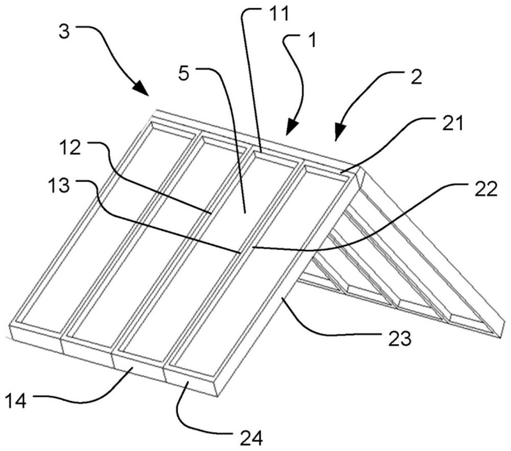
[0038] Figures 2 to 8 - First embodiment: panel structure in two-layer IGU, and various installation configurations

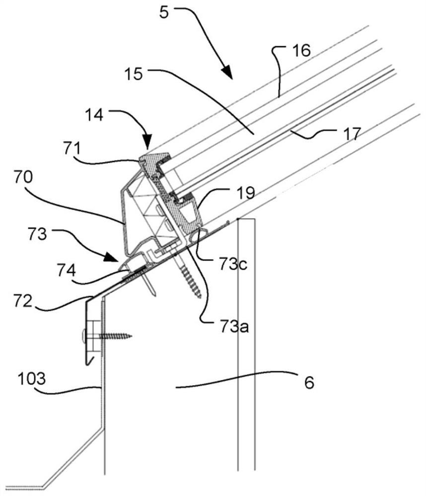
[0039] The principle of the structure of the profile element will now be described with reference to a first embodiment. It is pointed out that the described structure of the profile elements can in principle be applied to any one of the top profile element 11, the two side profile elements 12, 13 and the bottom profile element 14 of the fixed panel 1, and for possible Any one of the top profile element 21 , the two side profile elements 22 , 23 and the bottom profile element 24 of the panel 2 is opened.

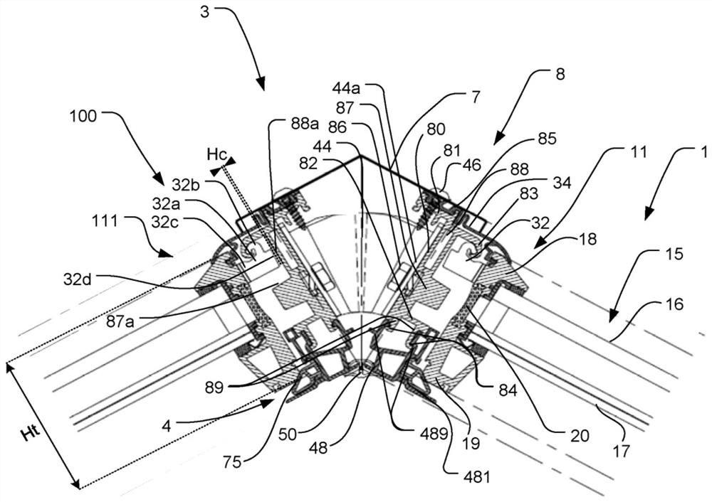
[0040] will refer to figure 2 The top profile element 11 is depicted in the cross-sectional view of the fixed panel 1 shown in and a second fixed panel 100 positioned opposite the fixed panel 1 . In the first installation configuration, the fixed panel 1 and the second fixed panel 100 can be formed as figure 1 Part of the panel system 3 shown in , i.e...

no. 2 approach

[0063] Figure 9 -Second embodiment: a panel structure in the form of a three-layer IGU

[0064] Figure 9 in with Figure 8 A second embodiment of the panel system 3 is shown in the corresponding view to the first embodiment. The panel system 3 of the second embodiment also comprises one or more fixed panels and one or more openable panels, wherein adjacent fixed panels 1 and openable panels 2 are shown. In this second embodiment, the paneling element 5 comprises a three-layer IGU 15' having three glass sheets, such that the three-layer IGU 15'

[0065] like Figure 8 and Figure 9 As shown in , the insulating member 20 is an elongated element comprising protrusions 20a at both ends. The insulating member 20 has a thickness T extending in an axial direction A, which is a plane parallel to the surface of the IGU 15 , ie to the outer pane 16 and the inner pane 17 . The heat insulating member 20 has a height H extending in the longitudinal direction L of the h...


PUM


Abstract

The invention relates to a panel system (3), comprising a plurality of fixed panels (1) and a plurality of openable panels (2). Each fixed panel (1) and each openable panel (2) comprise a frame structure consisting of a set of profile elements (11, 12, 13, 14, 21, 22, 23, 24) surrouding panel elements (5; 15; 15'), and said frame structure comprises a top profile element (11, 21) configured to be connected to a support structure by means of a mounting and hinge assembly. The mounting and hinge assembly comprises a mounting profile (9) and a hinge (25), and the hinge (25) is configured as a connecting element between the mounting profile (9) and the top profile elements (11, 21) of each fixed panel (1) and each openable panel (2).

Description

technical field [0001] The invention relates to a panel system comprising a plurality of fixed panels and a plurality of openable panels, each fixed and openable panel comprising a frame structure consisting of a set of profile elements surrounding the panel elements, said frame structure comprising into a top profile element connected to the supporting structure by means of mounting and hinge assemblies. Background technique [0002] Panel moldings, which include fixed or openable panels set in pitched or flat roofs, can be provided in many variations and often include complex structures to allow opening of the sash and perform other functions such as ventilation, waterproofing and thermal insulation, while Allows cleaning of the outside of the pane from inside the building. These include pivoting roof windows with hinge axes located at or displaced from the center of the window, and top-hung roof windows pivoted for cleaning by means of an intermediate frame. Additionall...

Claims


Application Information

Patent Timeline
IPC IPC(8): E04D13/035
CPCE04D13/0354
Inventor 比吉特·汉森
Owner VKR HLDG AS
Why Eureka
Try Eureka