
Tooling for preparing blade thermal barrier coating

A technology of thermal barrier coating and tooling, applied in metal material coating process, coating, vacuum evaporation coating, etc., can solve the problems of difficult control of deposited coating, uncontrollable swing speed, limited inclination angle, etc., to achieve Improve uniformity and strain tolerance, achieve thickness and structure control, and extend service life effects

Active Publication Date: 2022-05-20
BEIHANG UNIV +1
View PDF7 Cites 0 Cited by
  • Summary
  • Abstract
  • Description
  • Claims
  • Application Information

AI Technical Summary

Problems solved by technology

However, for workpieces with complex shapes, due to the occlusion area on the surface of the workpiece during the preparation of the coating, it is impossible to prepare a uniform and stable coating on the surface.
In particular, the guide vane has a complex profile, so it is difficult to use EB-PVD to prepare coatings on all parts of its surface
[0003] Chinese invention patent CN110760809B once provided a device that can realize the multi-degree-of-freedom rotation of the workpiece in the EB-PVD coating process, but the device provided by the invention can only make the workpiece swing in a small range, and the inclination angle of the workpiece is limited And the swing speed is uncontrollable, so that it is impossible to obtain a large range of steam incident angles on the edge plates on both sides of the guide vane at the same time, and the effect of improving the stability of the coating preparation process for workpieces with complex shapes such as guide vanes and turbine blades is not good.
[0004] Chinese invention patent CN110158047A discloses a support device for vapor deposition on the full channel surface of a guide vane and its application method. more difficult to control

Method used


Image

  • Tooling for preparing blade thermal barrier coating
  • Tooling for preparing blade thermal barrier coating
  • Tooling for preparing blade thermal barrier coating

Examples


Embodiment 1

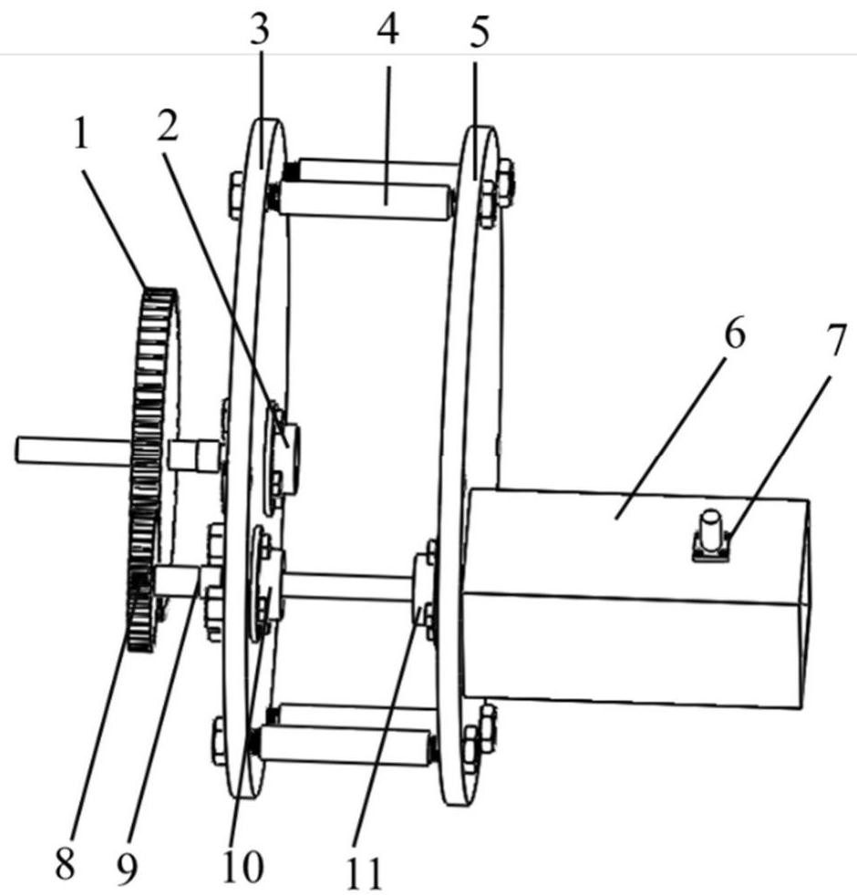
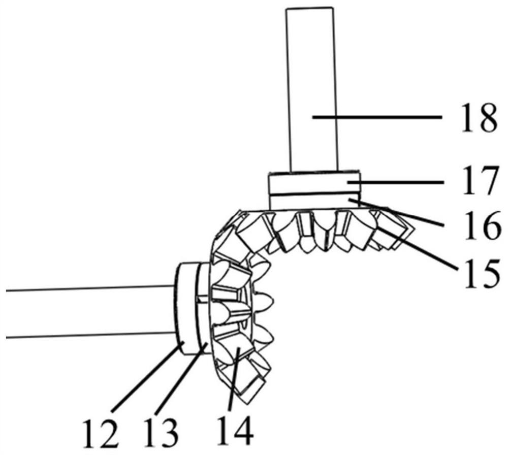
[0055] Using the tooling of the present invention, the guide vane and the sample rotation axis are fixed, and the coating is prepared by EB-PVD. The equipment swing main shaft drives the entire tooling to swing by ±50° through the change of the rotation direction; at the same time, the rotation of the main rotation axis drives the rotation of the slave rotation axis, thereby driving the rotation of the sample rotation axis, and finally drives the rotation of the guide vane connected to the sample rotation axis. Finally, it is realized that the guide vane can rotate and swing simultaneously during the preparation of the coating.

[0056] attached Figure 5 For the cross-sectional topography of the coating of the blade body part of the guide vane prepared by the tooling of the present invention, the coating can be prepared by using the tooling of the present invention to realize the preparation of a dense columnar crystal structure coating on the blade body of the guide vane.

...

Embodiment 2

[0060] Utilizing the tooling of the present invention, the turbine blade and the rotation axis of the device sample are fixed, and the swing main shaft of the EB-PVD equipment drives the entire tooling to swing within the range of 0 to 90° through the change of the rotation direction; at the same time, the rotation of the main rotation axis drives the rotation of the slave rotation axis, thereby Drive the rotation axis of the sample to rotate, and finally drive the guide blade connected with the rotation axis of the sample to rotate. Finally, the turbine blades can rotate and swing simultaneously during the preparation of the coating.

[0061] attached Figure 10 It is the cross-sectional appearance diagram of the coating of the turbine blade blade pot part prepared by the tooling of the present invention, attached Figure 11 For the cross-sectional topography of the coating on the back of the blade of the turbine blade prepared by the tooling of the present invention, from t...


PUM


Abstract

The invention provides a tooling for preparing a blade thermal barrier coating, which includes a swing system, a main rotation system, and a slave rotation system; the swing system drives the whole device to swing at a uniform speed, and then drives the samples to be deposited to swing; The system rotates, and the rotation system drives the sample to be deposited connected to it to rotate. The invention solves the problem in the prior art that the swing speed is uncontrollable, and it is impossible to obtain a large range of steam incident angles on the edge plates on both sides of the guide vane at the same time, and realizes the thickness and structure control of the blade body and edge plates. Improved coating microstructure uniformity and strain tolerance.

Description

technical field [0001] The invention relates to a device for preparing a blade thermal barrier coating, in particular to a tool for preparing an aeroengine guide blade thermal barrier coating by electron beam physical vapor deposition. Background technique [0002] Electron beam physical vapor deposition (EB-PVD) is a thermal protection technology for hot-end parts of aero-engines, especially for preparing thermal barrier coatings for guide vanes and high-pressure turbine blades. The "shadow effect" introduced by rotation during the preparation of thermal barrier coatings by EB-PVD can form a uniform coating with columnar grain microstructure on the surface of simple planar samples. However, for workpieces with complex shapes, a coating with uniform and stable structure cannot be prepared on the surface due to the shielding area on the surface of the workpiece during the preparation of the coating. In particular, the guide vane has a complex profile, so it is difficult to p...

Claims


Application Information

Patent Timeline
Patent Type & Authority Patents(China)
IPC IPC(8): C23C14/30C23C14/50C23C14/54C23C14/56
CPCC23C14/30C23C14/56C23C14/505C23C14/542Y02T50/60
Inventor 彭徽滕晓丹郭洪波宫声凯钱凌翼
Owner BEIHANG UNIV
Learn More