New energy automobile battery protection device facilitating heat dissipation

A new energy vehicle and protective device technology, which is applied to secondary batteries, battery pack components, and isolation of batteries from their environment, etc., can solve the problem of insufficient battery protection for new energy vehicles, inability to orient the cooling fan blowing route, and affecting new energy vehicles. battery and other problems, to achieve the effect of improving cooling efficiency and effectiveness, improving disaster survival rate, and increasing emergency response time

Active Publication Date: 2021-12-14
HIGER +1
View PDF13 Cites 0 Cited by
  • Summary
  • Abstract
  • Description
  • Claims
  • Application Information

AI Technical Summary

Problems solved by technology

[0003] At present, new energy vehicles are promoted to meet the needs of environmental protection and oil crisis, reduce or abandon the current mainstream models that burn traditional gasoline or diesel-driven internal combustion engines, but there are still some problems in the protective devices of new energy vehicle batteries inside existing new energy vehicles. To solve the problem, the existing protective devices usually use a cooling fan inside the battery structure of the new energy vehicle to achieve a wind-driven cooling effect in order to solve the battery overheating problem. Although this can achieve a certain effect in theory, the cooling fan itself There is heat generated during operation. After a certain period of use, its own heat may affect the new energy vehicle battery itself. Moreover, the blowing route of the cooling fan cannot be directed. Most of them are simply blowing directly on the battery. The actual effect is average. , Insufficient protection for new energy vehicle batteries

Method used


Image

  • New energy automobile battery protection device facilitating heat dissipation
  • New energy automobile battery protection device facilitating heat dissipation
  • New energy automobile battery protection device facilitating heat dissipation

Examples


Embodiment Construction

[0025] The following will clearly and completely describe the technical solutions in the embodiments of the present invention with reference to the accompanying drawings in the embodiments of the present invention. Obviously, the described embodiments are only some, not all, embodiments of the present invention. Based on the embodiments of the present invention, all other embodiments obtained by persons of ordinary skill in the art without making creative efforts belong to the protection scope of the present invention.

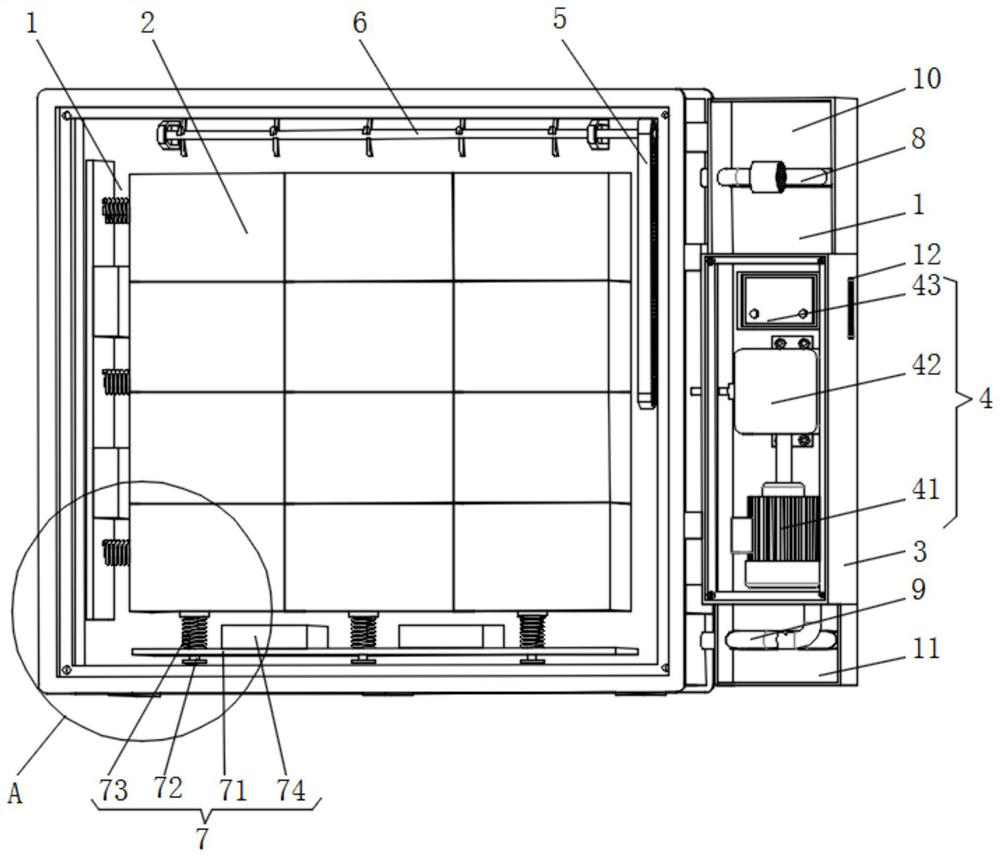
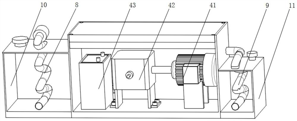
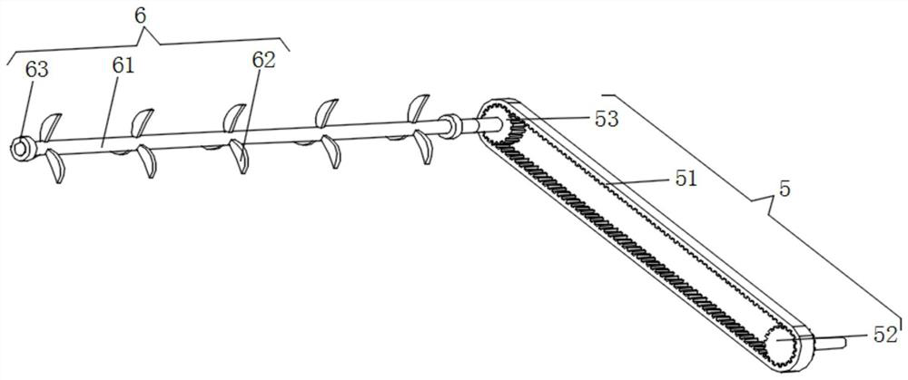
[0026] see figure 1 , image 3 , Figure 4 , Figure 5 , a protective device for a new energy vehicle battery that is conducive to heat dissipation, including a battery protection box 1, an automobile battery body 2 is sleeved inside the battery protection box 1, and an automobile battery body 2 is arranged between the surface of the vehicle battery body 2 and the inner wall of the battery protection box 1 There is a buffer mechanism 7, and the interior of ...


PUM


Abstract

The invention relates to the technical field of new energy automobiles, and discloses a new energy automobile battery protection device facilitating heat dissipation. The device comprises a battery protection box, an automobile battery body is sleeved in the battery protection box, and the reverse side and the side surface of one side of the automobile battery body are respectively provided with an air blowing mechanism and a tooth linkage mechanism. The output end of one side of the tooth linkage mechanism penetrates through the side wall of one side of the battery protection box and is movably sleeved at the penetrating part, and the output end of the other side of the tooth linkage mechanism and one end of the air blowing mechanism are mounted together. The auxiliary protection box, the power mechanism, the tooth linkage mechanism and the air blowing mechanism assembly are assembled into a composite transition type air cooling heat dissipation mechanism, compared with a traditional device, extra heat cannot be generated in the new energy automobile battery composed of the battery protection box and the automobile battery body, the air cooling heat dissipation effect is fully guaranteed, and the probability of faults caused by overheating of the battery of the new energy automobile is reduced.

Description

technical field [0001] The invention relates to the technical field of new energy vehicles, in particular to a protective device for a new energy vehicle battery which is beneficial to heat dissipation. Background technique [0002] New energy vehicles refer to vehicles that use unconventional vehicle fuels as power sources, integrate advanced technologies in vehicle power control and drive, and form vehicles with advanced technical principles, new technologies, and new structures. Existing new energy vehicles mainly Including four types of hybrid electric vehicles, pure electric vehicles, fuel cell electric vehicles, and other new energy vehicles. [0003] At present, new energy vehicles are promoted to meet the needs of environmental protection and oil crisis, reduce or abandon the current mainstream models that burn traditional gasoline or diesel-driven internal combustion engines, but there are still some problems in the protective devices of new energy vehicle batteries...

Claims


Application Information

Patent Timeline
Patent Type & Authority Applications(China)
IPC IPC(8): H01M50/249H01M50/209H01M50/24H01M50/244H01M10/613H01M10/625H01M10/6563H01M10/6565A62C3/16
CPCH01M50/249H01M50/209H01M50/24H01M50/244H01M10/613H01M10/625H01M10/6563H01M10/6565A62C3/16Y02E60/10
Inventor 李春赵振东黄应松文少波陈旭斌刘国庆
Owner HIGER
Why Eureka
Try Eureka