


Quick Research
Generate reliable direction feasibility study reports for your R&D in just a few steps.

Technical Q&A
Discover and master advanced knowledge NOW. Basics, ideas, possibilities, all at once.

Find Solutions
As an expert in R&D theories, this can generate solutions to your technical problems instantly.

Evaluate Feasibility
Analyze your overall solution with one click, know your potential R&D risks in advance.

Monitor Landscape
Get weekly tech updates, stay abreast of the latest tech innovations and key insights.
Electrified display device for GIS and GIS
A technology of live display device and mounting hole, which is applied in the direction of measuring device, measuring electrical variable, measuring current/voltage, etc., to achieve the effect of reducing leakage risk, improving stability and reducing the number of parts
- Summary
- Abstract
- Description
- Claims
- Application Information
AI Technical Summary
Problems solved by technology
Method used
Image

Examples
Embodiment 1
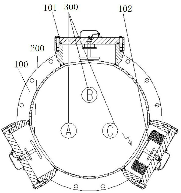
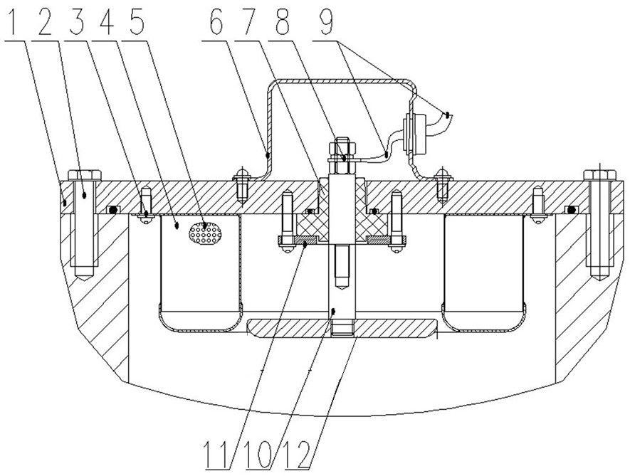
[0060] The structure of the GIS provided by this embodiment is as follows figure 1 and figure 2 As shown, the GIS housing 100 is included, and the three-phase GIS conductors 300 are arranged in the GIS housing 100, which are A-phase conductors, B-phase conductors and C-phase conductors respectively, and installation holes are respectively provided on the GIS housing 100 corresponding to the three-phase conductors 200, wherein the first charging display device 101 is respectively installed in the two installation holes 200 corresponding to the A-phase conductor and the B-phase conductor, and the second charging display device 102 is installed in the installation hole 200 corresponding to the C-phase conductor. The display device 101 and the second charging display device 102 are detachably fixed and installed at the openings of the corresponding mounting holes 200 respectively by bolts. The difference between the first charging display device 101 and the second charging displa...
specific Embodiment 2
[0073] The main difference between it and Embodiment 1 is that in Embodiment 1, the ring-shaped sieve frame makes the water adsorption structure a ring-shaped structure, which is convenient to fit outside the signal transmission rod. In this embodiment, the water adsorption structure may also be a plurality of independently distributed cube structures, including a square screen frame, and it is only necessary to arrange an adsorbent inside each screen frame.
specific Embodiment 3
[0075] The main difference between it and Embodiment 1 is that in Embodiment 1, the water adsorption structure adopts a screen frame structure, which facilitates the replacement of the internal adsorbent. In this embodiment, the water adsorption structure may also adopt a flexible mesh bag, and the flexible mesh bag is filled with an adsorbent to ensure effective adsorption and removal of water.
PUM
 Abstract
Description
Claims
Application Information
 - R&D Engineer
- R&D Manager
- IP Professional
- Industry Leading Data Capabilities
- Powerful AI technology
- Patent DNA Extraction
Browse by: Latest US Patents, China's latest patents, Technical Efficacy Thesaurus, Application Domain, Technology Topic, Popular Technical Reports.
© 2024 PatSnap. All rights reserved.Legal|Privacy policy|Modern Slavery Act Transparency Statement|Sitemap|About US| Contact US: help@patsnap.com