Soil temporary storage device for soil pollution diagnosis and capable of avoiding caking

A soil pollution and soil technology, applied in the field of soil pollution diagnosis, can solve problems such as easy sticking and agglomeration of soil, affecting detection work, and inability to clean out plant residues or stones, etc., to achieve easy cleaning, easy opening, and avoid soil pollution. caking effect

Active Publication Date: 2021-12-14
浙江湖畔湿地规划设计有限公司
View PDF7 Cites 0 Cited by
  • Summary
  • Abstract
  • Description
  • Claims
  • Application Information

AI Technical Summary

Problems solved by technology

[0003] The purpose of the present invention is to provide a soil temporary storage device for soil pollution diagnosis that avoids agglomeration, so as to solve the problem that the soil just taken out of the current temporary storage device on the market proposed by the above-mentioned background technology may be mixed with some plant residues or It is a stone, and the plant residue or stone cannot be cleaned out. When the existing soil temporary storage device is placed on the soil, the soil is easy to stick and agglomerate after a period of time, which affects the later detection work.

Method used


Image

  • Soil temporary storage device for soil pollution diagnosis and capable of avoiding caking
  • Soil temporary storage device for soil pollution diagnosis and capable of avoiding caking
  • Soil temporary storage device for soil pollution diagnosis and capable of avoiding caking

Examples


Embodiment Construction

[0029] The following will clearly and completely describe the technical solutions in the embodiments of the present invention with reference to the accompanying drawings in the embodiments of the present invention. Obviously, the described embodiments are only some, not all, embodiments of the present invention. Based on the embodiments of the present invention, all other embodiments obtained by persons of ordinary skill in the art without making creative efforts belong to the protection scope of the present invention.

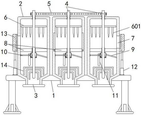
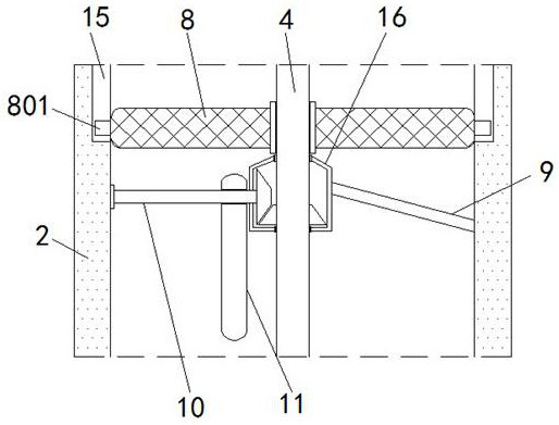
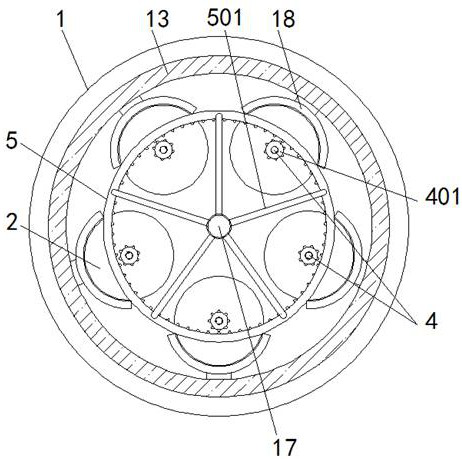
[0030] see Figure 1-8 , the present invention provides a technical solution: a soil temporary storage device for soil pollution diagnosis that avoids agglomeration, including a base body 1, a temporary storage bucket 2, a feeding port 3, a vertical rod 4, a transmission gear 401, and a ring gear body 5. Support rod 501, cross rod 6, crushing rod 601, feed port 7, filter plate 8, limit block 801, installation rod 9, connecting shaft rod 10, eccentric wheel 11,...


PUM


Abstract

The invention discloses a soil temporary storage device for soil pollution diagnosis and capable of avoiding caking. The soil temporary storage device comprises base main bodies, temporary storage barrels, discharging openings and a shielding plate, the temporary storage barrels are installed above the base main bodies with the circle centers of the base main bodies as the circle centers at equal intervals, the bottom ends of the temporary storage barrels penetrate through the bottom faces of the base main bodies, the discharging openings are formed in the bottom ends of the temporary storage barrels, vertical rods penetrate through the interiors of the top ends of the temporary storage barrels through bearings and are connected with the interiors of the top ends of the temporary storage barrels, transverse rods are fixed to the left side and the right side of the upper ends of the vertical rods through screws, filtering plates are arranged on the outer sides of the middles of the vertical rods in a nested mode, stirring rods are installed on the left sides and the right sides of the lower ends of the vertical rods through screws, and feeding openings are formed in the outer side surfaces of the temporary storage barrels. According to the soil temporary storage device, the filter plates are arranged, so that soil above the filter plates can be well shaken, then plant residues, stones and the like in the soil can be conveniently left on the filter plates, and the soil can be well used in the later period.

Description

technical field [0001] The invention relates to the technical field of soil pollution diagnosis, in particular to a temporary soil storage device for soil pollution diagnosis that avoids agglomeration. Background technique [0002] Soil pollution diagnosis refers to collecting soil and then testing it with sophisticated instruments, so as to know whether the soil is polluted or the degree of soil pollution. During the process of soil pollution diagnosis, the soil needs to be temporarily stored for later detection of the soil. For diagnostic work, although there are many types of temporary soil storage devices on the market, there are still some deficiencies in the process of use, such as: 1. The announcement number is "CN111114965A" and the patent title is "a soil placement device for soil layer weathering research based on soil detection", which solves the problem of existing soil collection equipment, which is usually directly loaded into collection bottles such as test t...

Claims


Application Information

Patent Timeline
IPC IPC(8): B02C19/00B02C23/16B07B1/34B07B1/42B07B1/46B65D25/00B65D25/52
CPCB02C19/0056B02C23/16B07B1/343B07B1/42B07B1/46B65D25/00B65D25/52B02C2023/165
Inventor 廖燕
Owner 浙江湖畔湿地规划设计有限公司
Why Eureka
Try Eureka