Eureka AIR delivers breakthrough ideas for toughest innovation challenges, trusted by R&D personnel around the world.

Method for integrating in-situ pyrolysis of oil-rich coal and geological storage of CO2

A technology of geological storage and in-situ pyrolysis, which is applied in the development of fluids, petroleum industry, earth-moving drilling, etc., can solve the problems of instability and leakage of geological bodies, and achieve the goal of increasing supply channels, increasing contact area, and improving recovery rate. Effect

Pending Publication Date: 2021-12-10
XIAN UNIV OF SCI & TECH
View PDF5 Cites 2 Cited by
  • Summary
  • Abstract
  • Description
  • Claims
  • Application Information

AI Technical Summary

Problems solved by technology

[0003] Existing CO 2 The geological storage method is to pressurize and inject carbon dioxide into the mines, natural gas reservoirs, oil fields and formations with large pore spaces that have been mined. This kind of method has the problem that the geological bodies after large-scale mining are unstable and prone to leakage

Method used


Image

  • Method for integrating in-situ pyrolysis of oil-rich coal and geological storage of CO2
  • Method for integrating in-situ pyrolysis of oil-rich coal and geological storage of CO2

Examples


Embodiment 1

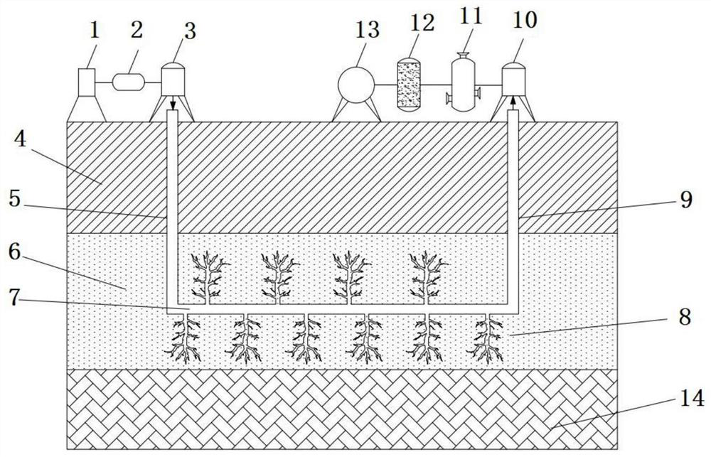
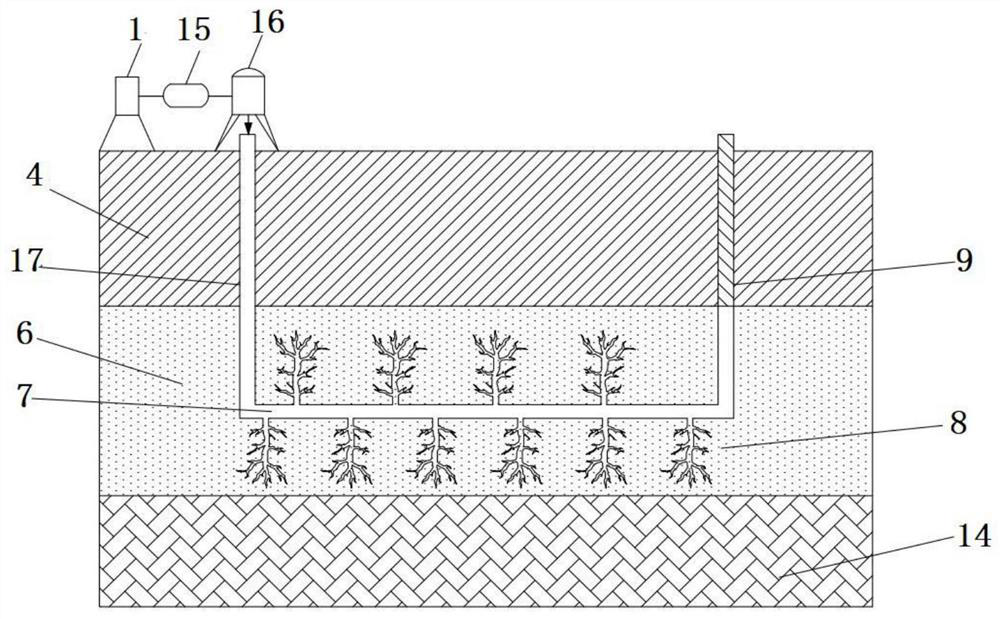
[0036] Such as figure 1 and figure 2 As shown, this embodiment includes the following steps:

[0037] Step 1, drilling along the coal seam roof 4 to the direction of the coal seam 6, respectively forming the injection well 5, the extraction well 9 and the horizontal well 7, and the injection well 5 and the extraction well 9 are connected through the horizontal well 7; the injection well 5 and the extraction well 9 both penetrate the coal seam roof 4 and enter the coal seam 6, and the horizontal well 7 is located in the coal seam 6 above the coal seam floor 14;

[0038] Step 2: Drill the coal seam surface of the horizontal well 7 formed in step 1 to form a borehole, and then use the energy supply in the energy harvesting device 1 to inject the fracturing fluid into the horizontal well 7 through the injection well 5 through the pressurizing device 2 And enter the borehole to pressurize, so that the coal seam at the drillhole position is cracked to form a fracture 8, and then ...

Embodiment 2

[0045] The difference between this embodiment and Embodiment 1 is that the pyrolysis thermodynamic system in step 2 includes a heating rod arranged in the borehole of the horizontal well 7; the process of said heating and pyrolysis is: start the heating rod to The coal seam in Hirai 7 is heated and pyrolyzed to obtain pyrolysis solid products and pyrolysis gas products.


PUM


Abstract

The invention discloses a method for integrating in-situ pyrolysis of oil-rich coal and geological storage of CO2. The method comprises the following steps that 1, drilling is achieved to form an injection well, an extraction well and a horizontal well, and the injection well communicates with the extraction well through the horizontal well; 2, holes are drilled in the surface of a coal seam of the horizontal well, then heating and pyrolyzing are achieved by adopting a pyrolysis thermodynamic system, and the obtained pyrolysis gas product is treated in an oil gas collection and separation system; and 3, a pyrolysis technology in the second step is repeated, after the pyrolysis technology is finished, supercritical CO2 is injected through a sealing heat power system and adsorbed on the pyrolysis solid product in a drill hole, and the CO2 geological storage process is completed. According to the method for integrating in-situ pyrolysis of the oil-rich coal and geological storage of the CO2, the oil-rich coal in the coal seam is subjected to in-situ heating pyrolysis to be converted into oil gas, then the CO2 is fully adsorbed through pyrolysis solid products for CO2 geological storage, integration of in-situ pyrolysis of the oil-rich coal and the geological storage of the CO2 is achieved, green and safe mining and utilization of coal are achieved, and the pyrolysis and storage cost is reduced.

Description

technical field [0001] The invention belongs to the technical field of oil-rich coal development, in particular to an in-situ pyrolysis of oil-rich coal and CO 2 An integrated approach to geological storage. Background technique [0002] At present, most of the more mature coal pyrolysis technologies are pyrolysis technologies based on surface technology. This type of technology is to mine coal and transport it to the ground for pyrolysis. This technology can realize clean and efficient utilization of coal, but it needs to be It costs a lot of manpower, material and financial resources, and there are problems such as high mining risk and low utilization rate of pyrolysis solid products. Therefore, in-situ coal pyrolysis is expected to become an important method for green and low-carbon development of coal. [0003] Existing CO 2 The geological storage method is to pressurize and inject carbon dioxide into the mines, natural gas reservoirs, oil fields and formations with la...

Claims


Application Information

Patent Timeline
IPC IPC(8): E21F17/16E21B43/30E21B43/34C10B53/04C10B49/02
CPCE21F17/16E21B43/305E21B43/34C10B53/04C10B49/02
Inventor 王双明崔世东王绪正师庆民王生全孙强
Owner XIAN UNIV OF SCI & TECH
Why Eureka
Eureka Blog
Learn More