Drive axle assembly with main speed reducer parking structure
A technology of drive axle assembly and main reducer, which is applied to axles, wheels, brakes, etc., to achieve the effects of reduced development costs, simple structure, and reliable effects
- Summary
- Abstract
- Description
- Claims
- Application Information
AI Technical Summary
Problems solved by technology
Method used
Image
Examples
Embodiment Construction
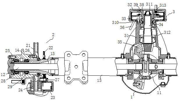
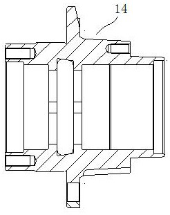
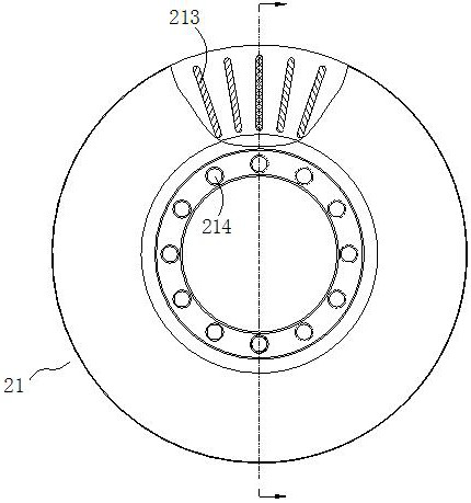
[0028] Such as Figure 1 to Figure 5 As shown, a drive axle assembly with a parking structure of the final drive includes a drive axle housing 1, a half shaft 12 connected to the output end of the differential 11 in the drive axle housing 1, and is sleeved on the half shaft 12 The outer half shaft sleeve 13, the wheel hub 14 installed on the half shaft sleeve 13, the service brake mechanism 2 installed on the side of the wheel hub 14 and the parking brake mechanism 3 installed on the final reducer shell 31, the drive The brake mechanism 2 includes a brake disc 21 installed on one side of the hub 14, a flange 22 installed on the half shaft sleeve 13, and a caliper 23 installed on the flange 22. The caliper 23 has two opposite The friction plates 24 are located on both sides of the brake disc 21, and the two friction plates 24 are connected to the brake cylinder;
[0029] Wherein, the hub 14 , the brake disc 21 and the flange 22 are installed coaxially, and the flange 22 is fix...
PUM
 Abstract
Description
Claims
Application Information
 - R&D
- Intellectual Property
- Life Sciences
- Materials
- Tech Scout
- Unparalleled Data Quality
- Higher Quality Content
- 60% Fewer Hallucinations
Browse by: Latest US Patents, China's latest patents, Technical Efficacy Thesaurus, Application Domain, Technology Topic, Popular Technical Reports.
© 2025 PatSnap. All rights reserved.Legal|Privacy policy|Modern Slavery Act Transparency Statement|Sitemap|About US| Contact US: help@patsnap.com


