Portable biological amniotic membrane shearing device
A shearing device and portable technology, applied in the field of portable biological amniotic membrane shearing devices, can solve the problems of easy delay, inconvenient transportation and cleaning of cutting tools, uneven shearing surface of amniotic membrane, etc.
- Summary
- Abstract
- Description
- Claims
- Application Information
AI Technical Summary
Problems solved by technology
Method used
Image
Examples
Embodiment 1
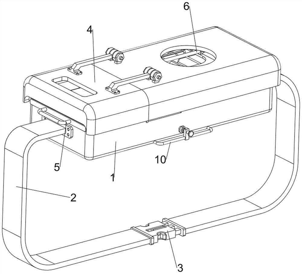
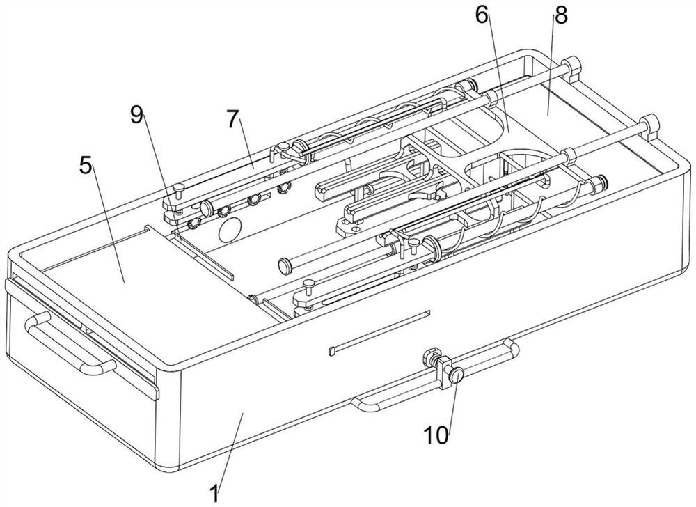
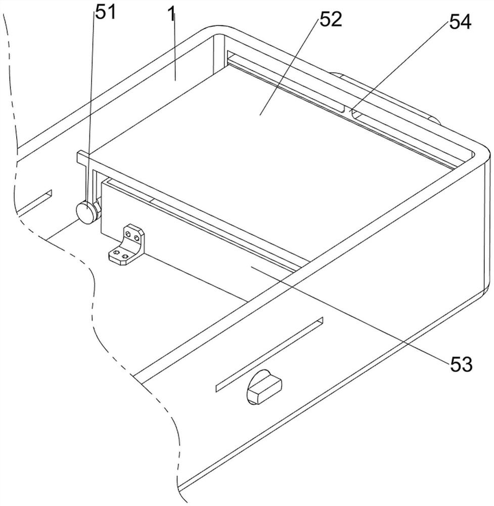
[0038] A portable biological amnion shearing device, such as Figure 1-6 As shown, it includes a casing 1, a strap 2, a buckle 3, a rotating frame 4, a charging mechanism 5, and a shearing mechanism 6. The casing 1 is symmetrically provided with a strap 2, and the bottom of the left strap 2 is provided with a buckle 3. The buckle 3 cooperates with the strap 2 on the right side, the top left side of the housing 1 is rotated and provided with a rotating frame 4, the rotating frame 4 cooperates with the housing 1, a charging mechanism 5 is provided on the left side of the housing 1, and the upper right side of the housing 1 is away from the The position of the charging mechanism 5 is provided with a shearing mechanism 6, and the left side of the rotating frame 4 is provided with a glass window, which is convenient for viewing the situation inside the housing 1.
[0039] When people need to cut the amniotic membrane, because the device is relatively heavy, people can open the buck...
Embodiment 2
[0045] On the basis of Example 1, such as figure 1 , figure 2 , Figure 7 , Figure 8 , Figure 9 , Figure 10 , Figure 11 , Figure 12 , Figure 13 , Figure 14 , Figure 15 , Figure 16 , Figure 17 and Figure 18 As shown, clamping mechanism 7 is also included, and clamping mechanism 7 includes first connecting rod 71, fixed plate 72, slide plate 73, second spring 74, second fixed rod 75 and third fixed rod 76, cutter 62 The right side is symmetrically provided with the first connecting rod 71 front and rear, and the left side of the first connecting rod 71 is slidingly provided with a fixed plate 72. There are two fixed plates 72, and the fixed plate 72 on the same side and the first connecting rod on the same side The 9th spring is all connected between 71, and the fixed plate 72 lower sides are all slidably provided with sliding plate 73, and there are two sliding plates 73, and two springs are connected between the sliding plate 73 on the same side and the...
PUM
 Abstract
Description
Claims
Application Information
 - R&D
- Intellectual Property
- Life Sciences
- Materials
- Tech Scout
- Unparalleled Data Quality
- Higher Quality Content
- 60% Fewer Hallucinations
Browse by: Latest US Patents, China's latest patents, Technical Efficacy Thesaurus, Application Domain, Technology Topic, Popular Technical Reports.
© 2025 PatSnap. All rights reserved.Legal|Privacy policy|Modern Slavery Act Transparency Statement|Sitemap|About US| Contact US: help@patsnap.com


