Advanced premixing abrasive water jet equipment and generation method

An abrasive water jet and pre-mixing technology, applied in the field of abrasive water jet, can solve the problems of insufficient acceleration, long abrasive acceleration time, short abrasive acceleration time, etc., and achieve the effects of simple device, long acceleration time, and short acceleration time.

Active Publication Date: 2021-12-10
HENAN POLYTECHNIC UNIV
View PDF8 Cites 2 Cited by
  • Summary
  • Abstract
  • Description
  • Claims
  • Application Information

AI Technical Summary

Problems solved by technology

Since the post-mixed abrasive water jet cannot fully mix the abrasive with the high-speed flowing water, the transmission efficiency of the aqueous medium to the abrasive is significantly reduced, and the acceleration time for the abrasive is short and insufficient. Therefore, in rock excavation, drilling and mining, etc. On the one hand, the post-mixed abrasive water jet has poor rock-breaking ability, coupled with the limitations of the engineering environment, it is impossible to use the post-mixed abrasive water jet
At the same time, although the pre-mixed abrasive water jet is uniformly mixed, and the abrasive acceleration time is long, the coal-breaking effect is better, but a key problem that limits the large-scale application of the pre-mixed abrasive water jet is the problem of continuous abrasive feeding; When water jet and post-mixed abrasive water jet are used to break coal and rock, the water cushion effect is more obvious, the energy utilization rate is lower, and the effect of breaking coal and rock is worse than that of pulsed abrasive water jet.
[0003] In order to realize the real continuous feeding of the front mixing abrasive jet, "a double tank double pump type front mixing abrasive jet continuous working system" (CN107953270B) uses two high-pressure abrasive tanks and two high-pressure water pumps to work alternately to realize continuous feeding. material, but the structure of this equipment is complicated, and the sand mixing ratio cannot be precisely controlled. At the same time, the working system is a continuous jet, and the water cushion effect is obvious.

Method used


Image

  • Advanced premixing abrasive water jet equipment and generation method
  • Advanced premixing abrasive water jet equipment and generation method
  • Advanced premixing abrasive water jet equipment and generation method

Examples


Embodiment Construction

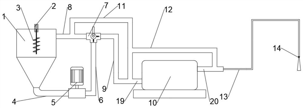
[0047] see Figure 1~5 , the present invention provides an advanced pre-mixed abrasive water jet equipment, including: mixing tank 1, agitator 3, feeding pump 5, grouting pump 10 and nozzle 14;

[0048] Wherein, the stirring tank 1 is provided with a stirrer 3 capable of circulating stirring inside;

[0049] The bottom of the mixing tank 1 is communicated with the input end of the feed pump 5 using a pipeline-4;

[0050] The output end of the feed pump 5 is communicated with the liquid inlet end of the three-way ball valve 7 using a pipeline two 6;

[0051] One of the liquid outlets of the three-way ball valve 7 is connected to the mixing tank 1 through the pipeline three 8, and the other liquid outlet is connected to the grouting pump inlet 19 of the grouting pump 10 through the pipeline four 9 ;

[0052] The grouting pump outlet of described grouting pump 10 adopts high-pressure hose 13 to be connected with nozzle 14, by arranging high-pressure hose 13, it is convenient to ...


PUM


Abstract

The invention discloses advanced premixing abrasive water jet equipment and a generation method. The advanced premixing abrasive water jet equipment comprises a stirring barrel, a stirrer, a feeding pump, a grouting pump and a nozzle; the stirrer capable of circularly stirring the interior of the stirring barrel is arranged in the stirring barrel; the bottom of the stirring barrel communicates with the input end of the feeding pump through a first pipeline; the output end of the feeding pump communicates with the liquid inlet end of a three-way ball valve through a second pipeline; one liquid outlet end of the three-way ball valve communicates with the stirring barrel through a third pipeline, and the other liquid outlet end of the three-way ball valve communicates with a grouting pump feeding port of the grouting pump through a fourth pipeline; and a grouting pump discharging port of the grouting pump communicates with the nozzle through a high-pressure hose.

Description

technical field [0001] The invention relates to the technical field of abrasive water jets, in particular to an advanced pre-mixed abrasive water jet equipment and a generating method. Background technique [0002] Abrasive water jet technology is a new technology developed in modern times, which is widely used in industrial cutting, rock excavation, surface cleaning and drilling. According to different feeding methods, abrasive water jets are divided into pre-mixed abrasive water jets and post-mixed abrasive water jets. Since the post-mixed abrasive water jet cannot fully mix the abrasive with the high-speed flowing water, the transmission efficiency of the aqueous medium to the abrasive is significantly reduced, and the acceleration time for the abrasive is short and insufficient. Therefore, in rock excavation, drilling and mining, etc. On the one hand, the post-mixed abrasive water jet has poor rock-breaking ability, and coupled with the limitations of the engineering en...

Claims


Application Information

Patent Timeline
Patent Type & Authority Applications(China)
IPC IPC(8): B24C1/04B24C3/04B24C7/00
CPCB24C1/045B24C3/04B24C7/0023
Inventor 刘勇魏建平刘笑天姚邦华张宏图徐向宇司磊磊代硕张东鑫李海超
Owner HENAN POLYTECHNIC UNIV
Why Eureka
Try Eureka