
Elevator system with grounded elevator car

A technology for elevators and equipment, applied in the field of elevator equipment, to achieve low wear, prevent interruptions, and good long-term stability

Active Publication Date: 2021-12-07
TK ELEVATOR INNOVATION & OPERATIONS GMBH
View PDF6 Cites 0 Cited by
  • Summary
  • Abstract
  • Description
  • Claims
  • Application Information

AI Technical Summary

Problems solved by technology

However this would require the use of significantly more expensive electrical components in the car electrical installation
In addition, there is still a second problem, the risk of discharge via passengers

Method used


Image

  • Elevator system with grounded elevator car
  • Elevator system with grounded elevator car
  • Elevator system with grounded elevator car

Examples


Embodiment Construction

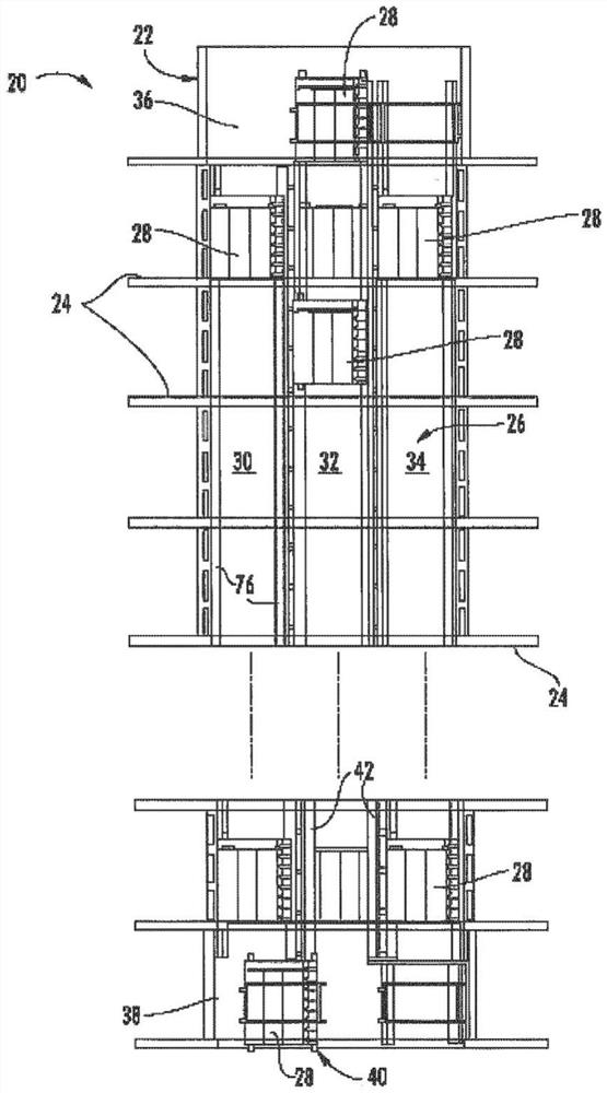
[0030] figure 1 An exemplary embodiment of a cordless elevator installation 20 is shown, which can be used in a structure or building 22 with different levels or floors 24 . The elevator installation 20 comprises an elevator shaft 26 and at least one cage 28 movable in the direction of travel in the elevator shaft. For example, elevator hoistway 26 may include three travel lanes 30 , 32 , 34 . In this case, any number of cars 28 can travel along one of the roadways 30 , 32 , 34 in any direction of travel (up or down). For example, as shown, cabs 28 on traffic lanes 30 and 34 may travel upward, while cabs 28 on traffic lane 32 may travel downward. Above the uppermost floor 24 there is an upper transfer device 36 which can transfer the car 28 between the carriageways 30 , 32 , 34 . Below the lowest floor 24 there is a lower transfer device 38 which likewise enables the transfer of the car 28 between the carriageways 30 , 32 , 34 . It is of course equally possible that the up...


PUM


Abstract

The invention relates to an elevator system comprising at least one elevator car (28) that can be moved in an elevator shaft along a guide rail (52). At least one first roller (54) is arranged between the elevator car (28) and guide rails (52), said first roller (54) being designed as a grounding roller. In this way, the elevator car (28) is prevented from being electrostatically charged during travel.

Description

technical field [0001] The invention relates to an elevator installation having at least one cage which can be moved in the direction of travel along an elevator shaft. Background technique [0002] Elevator installations are used to transport passengers between different floors of a building. For this purpose, the car is moved between the floors inside the elevator shaft. For this purpose, the car is usually connected to the counterweight by means of carrying ropes which run over driven drive discs. In contrast to this, alternative elevator installations do not use counterweights and are driven by means of linear drives which are integrated in the rails and the car. The car is then, for example, equipped with permanent magnets, which apply a magnetic field via coils arranged along the elevator shaft. Thereby, the driving force is transmitted to the car. Additionally, conventional cars are connected to the hoistway walls of the elevator shaft by suspension cables. The e...

Claims


Application Information

Patent Timeline
Patent Type & Authority Applications(China)
IPC IPC(8): B66B7/04
CPCB66B7/046
Inventor 马丁·马德拉迈克尔·基尔施菲利普·盖恩奇于尔根·弗兰特泽尔德托马斯·格奥尔格·霍恩马克斯·梅尔
Owner TK ELEVATOR INNOVATION & OPERATIONS GMBH
Learn More