High-power-density transverse magnetic field electromagnetic linear actuator

A high power density, linear actuator technology, applied in magnetic circuits, electrical components, electromechanical devices, etc., can solve the problem of limiting the application of transverse magnetic field electromagnetic linear actuators, increasing the structural complexity of transverse magnetic field actuators, and the difficulty of manufacturing processes, etc. problem, to achieve the effect of reducing nonlinear output, simple structure, and strong current controllability

Pending Publication Date: 2021-12-07
SHANDONG UNIV OF TECH
View PDF0 Cites 0 Cited by
  • Summary
  • Abstract
  • Description
  • Claims
  • Application Information

AI Technical Summary

Problems solved by technology

However, due to the inherent spatial three-dimensional magnetic circuit characteristics of transverse magnetic field actuators, the manufacturing process is difficult, which increases the structural complexity of transverse magnetic field actuators and limits the application of transverse magnetic field electromagnetic linear actuators.
[0004] In order to simplify the processing technology, save manufacturing cost, and solve the low power density problem of the traditional cylindrical longitudinal magnetic field actuator, a high power density transverse magnetic field electromagnetic linear actuator structure of the present invention is proposed, which can ensure the control accuracy and reduce the Under the influence of the coupling of dynamic characteristics, the nonlinear output is greatly reduced, and the power density, working reliability and wide application of the actuator are improved.

Method used


Image

  • High-power-density transverse magnetic field electromagnetic linear actuator
  • High-power-density transverse magnetic field electromagnetic linear actuator

Examples


Embodiment Construction

[0017] In order to make the purpose, technical solutions and advantages of the embodiments of the present invention clearer, the technical solutions in the embodiments of the present invention will be clearly and completely described below in conjunction with the drawings in the embodiments of the present invention. Obviously, the described embodiments It is a part of embodiments of the present invention, but not all embodiments. Based on the embodiments of the present invention, all other embodiments obtained by persons of ordinary skill in the art without making creative efforts belong to the protection scope of the present invention.

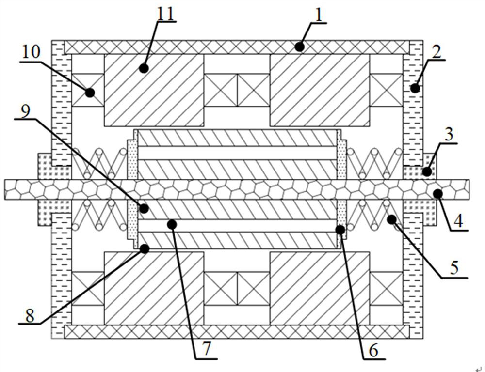
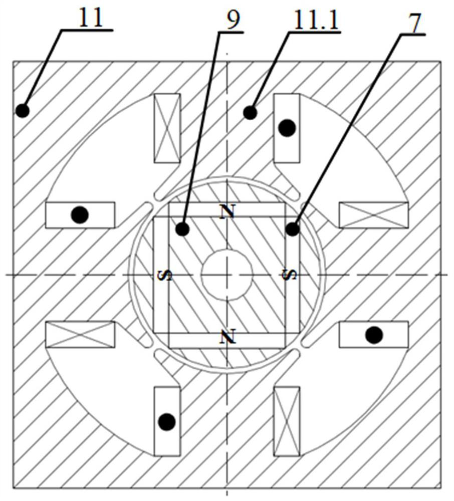
[0018] Such as figure 1 As shown, a high power density transverse magnetic field electromagnetic linear actuator includes: housing (1), end support cover (2), linear bearing (3), output shaft (4), resonant spring (5), isolation Magnetic ring (6), permanent magnet (7), air gap (8), mover core (9), stator winding (10), stator core (11) and sta...


PUM


Abstract

The invention relates to a high-power-density transverse magnetic field electromagnetic linear actuator which comprises a shell, an end supporting cover, a linear bearing, an output shaft, a resonance spring, a magnetism isolating ring, a permanent magnet, a rotor iron core, a stator winding, a stator iron core and stator iron core teeth, and is characterized in that the stator iron core is installed in the shell, and the permanent magnet is embedded in the rotor iron core; the rotor iron core is installed on the output shaft and fixed to the end supporting covers on the two sides, the magnetism isolating rings are installed at the two ends of the rotor iron core in a pressed mode, and the portions, between the magnetism isolating rings and the end supporting covers, of the output shaft are sleeved with the resonance springs. During working, current is introduced into the stator winding to generate a non-uniform air-gap magnetic field, a resonance system composed of the permanent magnet, the rotor iron core, the resonance spring and the output shaft is driven to do linear motion, and driving force is generated and drives a load to operate. According to the invention, driving and control of a high-speed and high-precision linear direct motion system are realized, and high-power-density operation and required driving capability of an actuator are ensured at the same time.

Description

technical field [0001] The invention relates to the technical field of motors, in particular to a high power density transverse magnetic field electromagnetic linear actuator. Background technique [0002] As an energy conversion device and a drive-controlled actuator, the electromagnetic linear actuator can convert one or more types of energy into mechanical energy that directly outputs linear motion, and has obvious advantages in quality, volume and response. , are widely used in applications such as short stroke, large driving force and smooth feed. [0003] At this stage, the traditional cylindrical longitudinal magnetic field actuator reduces its power density and control accuracy due to the cross-coupling effect between the loads; while the transverse magnetic field actuator effectively solves the coupling relationship between the loads and improves the performance of the actuator. High power density, and the decoupling feature is convenient for miniaturization design...

Claims


Application Information

Patent Timeline
Patent Type & Authority Applications(China)
IPC IPC(8): H02K41/03H02K16/04H02K1/14H02K3/28
CPCH02K41/031H02K16/04H02K1/14H02K3/28H02K2213/03H02K2201/12
Inventor 吕治强葛文庆谭草陆佳瑜
Owner SHANDONG UNIV OF TECH
Why Eureka
Try Eureka