Combined system of low-voltage electrical complete equipment

A complete set of equipment and combined system technology, applied in the direction of electrical components, substation/switchgear cooling/ventilation, substation/switch arrangement details, etc., can solve the problem of single heat dissipation method, unfavorable safe use of electrical components, poor heat dissipation effect, etc. problem, achieve the effect of saving electric energy and improving the effect of heat dissipation

Inactive Publication Date: 2021-12-07
刘帅
View PDF0 Cites 0 Cited by
  • Summary
  • Abstract
  • Description
  • Claims
  • Application Information

AI Technical Summary

Problems solved by technology

[0004] The purpose of the present invention is to provide a combined system of low-voltage electrical complete sets of equipment, through a complete box body, a heat dissipation installation structure, a split flow heat dissipation assembly, a first installation mechanism, a second installation mechanism, a positioning assembly, a heat dissipation fixing assembly and an air volume adjustment assembly The design solves the problem that the existing low-voltage electrical complete sets of equipment have a single heat dissipation method, and the air volume cannot be flexibly adjusted according to heat dissipation requirements, resulting in poor heat dissipation effect, which is not conducive to the safe use of electrical components, and cannot realize separate heat dissipation of multiple electrical components , and it is impossible to realize the automatic control of heat dissipation according to the local heat of electric components, which is not conducive to the problem of saving electric energy

Method used


Image

  • Combined system of low-voltage electrical complete equipment
  • Combined system of low-voltage electrical complete equipment
  • Combined system of low-voltage electrical complete equipment

Examples


Embodiment Construction

[0041] The following will clearly and completely describe the technical solutions in the embodiments of the present invention with reference to the accompanying drawings in the embodiments of the present invention. Obviously, the described embodiments are only some, not all, embodiments of the present invention. Based on the embodiments of the present invention, all other embodiments obtained by persons of ordinary skill in the art without creative efforts fall within the protection scope of the present invention.

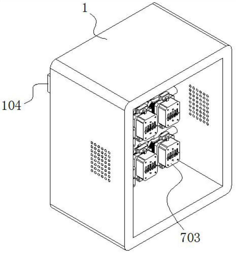
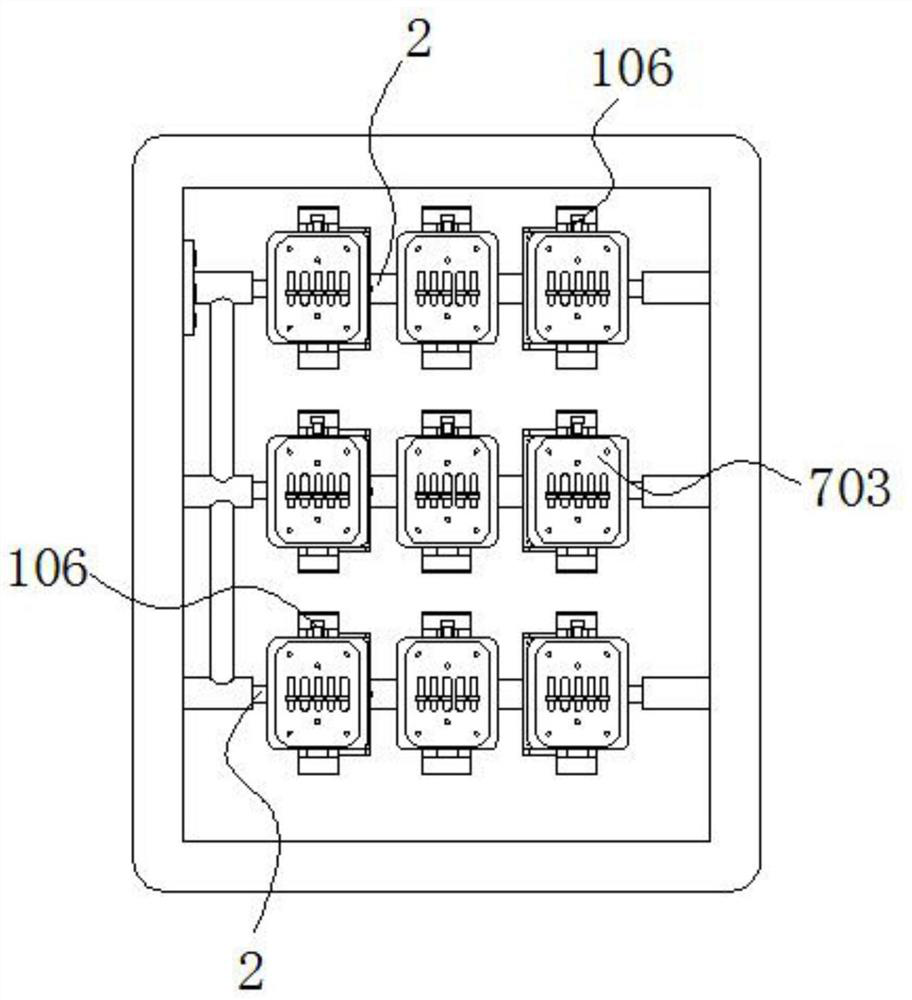
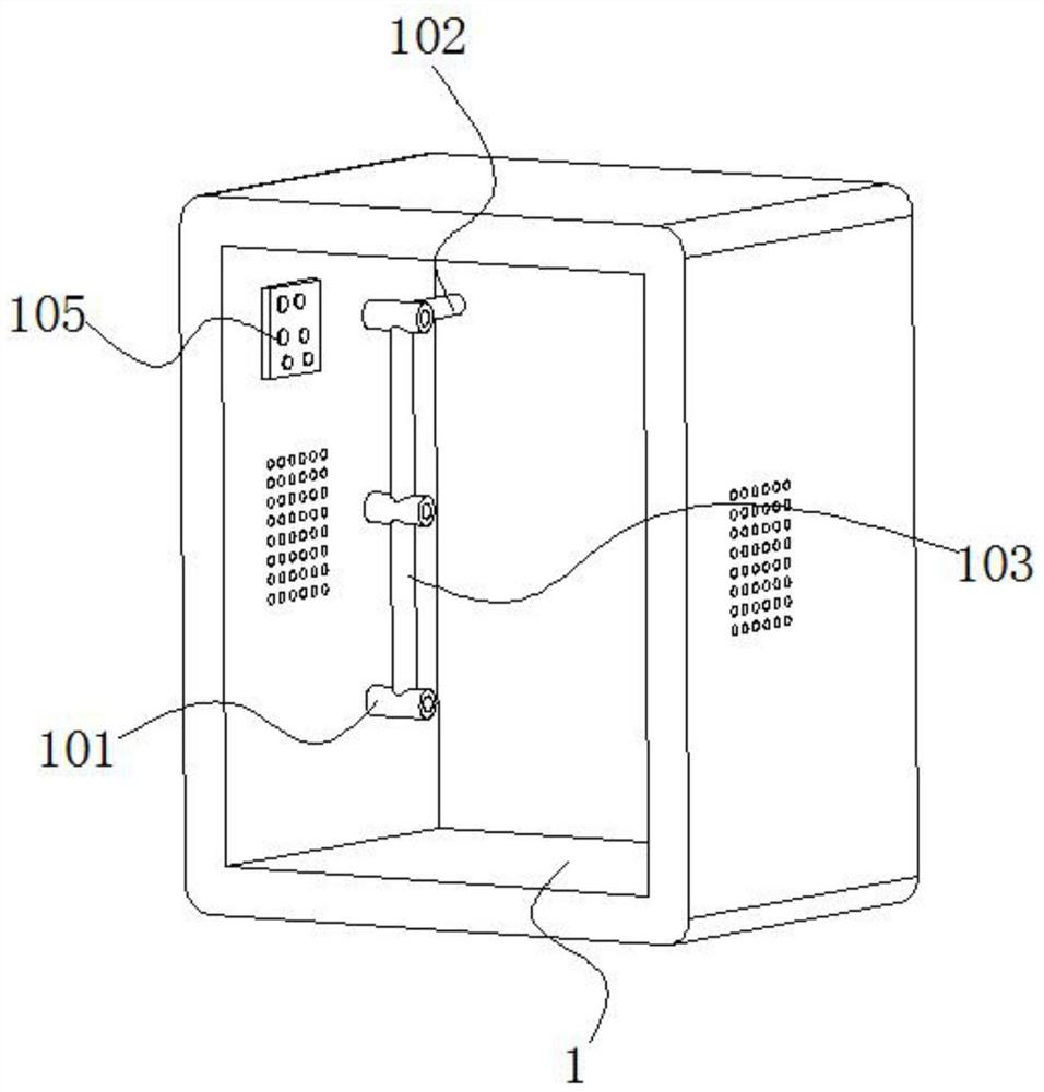
[0042] see Figure 1-16 , the present invention is a combined system of low-voltage electrical complete sets of equipment, including a complete set of box body 1; the complete set of box body 1 has a number of hollow sleeve columns 101 arrayed on the opposite inner sides, and a heat dissipation installation is arranged between the two hollow sleeve columns 101 Structure 2; one side of the hollow column 101 is connected with an air duct 102 through the side, and the...


PUM


Abstract

The invention discloses a combined system of low-voltage electrical complete equipment, and relates to the technical field of electric power. The equipment comprises a complete box body, hollow sleeve columns are arranged on the two opposite inner side faces of the complete box body in an array mode, and a heat dissipation type installation structure is arranged between the two opposite hollow sleeve columns. The heat dissipation type installation structure is composed of a shunting heat dissipation assembly, a first installation mechanism, a second installation mechanism and a positioning assembly. The positioning assembly is in threaded fit with the exterior of the shunting heat dissipation assembly, and the first mounting mechanism and the second mounting mechanism are both mounted on the shunting heat dissipation assembly; and the first mounting mechanism and the second mounting mechanism are each composed of a heat dissipation fixing assembly and an air volume adjusting assembly. Through the design of the heat dissipation fixing assembly, the ventilation limiting piece, the gear, the through hole channel and the air volume adjusting assembly, the sealing disc of the air volume adjusting assembly is driven to slide in the through hole channel through the cooperation effect of the gear and the rack, and therefore the size of a ventilation opening of the ventilation limiting piece is adjusted, and the air volume can be flexibly adjusted according to the heat dissipation requirement.

Description

technical field [0001] The invention belongs to the field of electric power technology, and in particular relates to a combined system of low-voltage electrical complete equipment. Background technique [0002] As one of the most important energy sources in today's society, electric power is very important in daily life and production. When electric power is supplied to the operation of equipment, it generally needs to undergo voltage transformation, shunting, control and other operations to meet the needs of the equipment. , which requires complete sets of high and low voltage electrical equipment to realize the transformation, shunting, control, etc. of electrical power, especially the use of low voltage electrical equipment. [0003] However, the inventors of the present application found that the low-voltage electrical complete sets of equipment in the prior art still have the following problems in the process of implementing specific embodiments of the present invention...

Claims


Application Information

Patent Timeline
Patent Type & Authority Applications(China)
IPC IPC(8): H02B1/56H02B1/48
CPCH02B1/565H02B1/48
Inventor 刘帅
Owner 刘帅
Why Eureka
Try Eureka