Testing device

A technology of testing device and installation cavity, applied in the direction of measuring device, measuring device casing, measuring electricity, etc., can solve the problems of unstable resistance test result, easy shaking of probe head, low probe life, etc. The effect of measuring rate, ensuring accuracy, and improving aesthetics

Pending Publication Date: 2021-12-03
GOERTEK INC
View PDF15 Cites 0 Cited by
  • Summary
  • Abstract
  • Description
  • Claims
  • Application Information

AI Technical Summary

Problems solved by technology

[0003] In related technologies, when performing resistance testing, the test surface of the watch is sometimes inclined and the test surface is small, and the anode layer around the test surface is not conductive. When the test device uses a probe to directly test the product, the probe head is easy to Shaking touches the surrounding anode layer, resulting in unstable resistance test results and low probe life

Method used


Image

  • Testing device
  • Testing device
  • Testing device

Examples


Embodiment Construction

[0054] The following will clearly and completely describe the technical solutions in the embodiments of the present invention with reference to the accompanying drawings in the embodiments of the present invention. Obviously, the described embodiments are only part of the embodiments of the present invention, not all of them. Based on the embodiments of the present invention, all other embodiments obtained by persons of ordinary skill in the art without creative efforts fall within the protection scope of the present invention.

[0055]It should be noted that all directional indications (such as up, down, left, right, front, back...) in the embodiments of the present invention are only used to explain the relationship between the components in a certain posture (as shown in the accompanying drawings). Relative positional relationship, movement conditions, etc., if the specific posture changes, the directional indication will also change accordingly.

[0056] At the same time, ...


PUM


Abstract

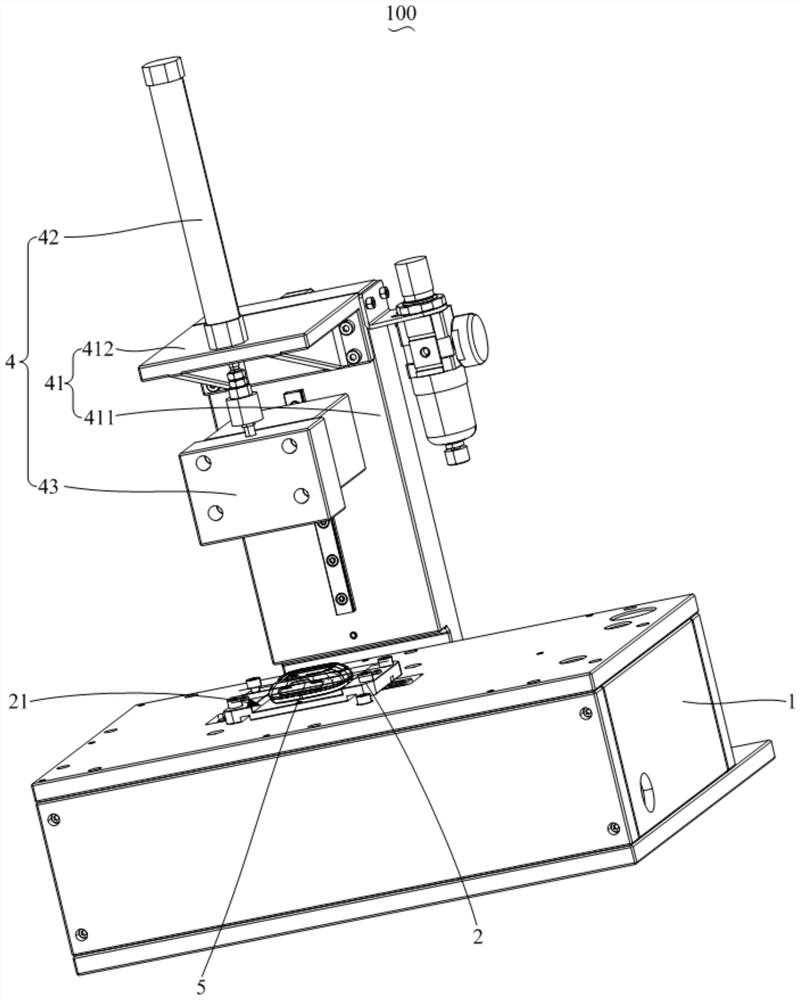
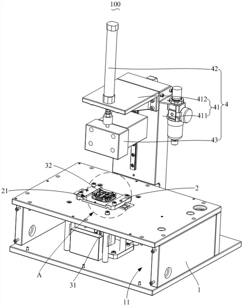
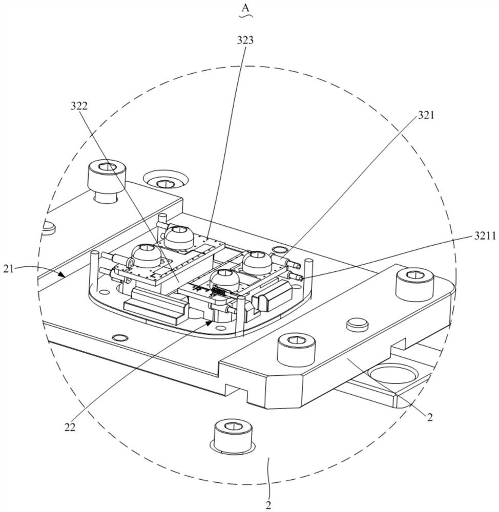
The invention relates to a testing device, which comprises a machine body, a positioning jig and a detection mechanism, the machine body is provided with a mounting cavity and a through hole communicated with the mounting cavity, the positioning jig is connected to the machine body, the positioning jig is provided with a positioning groove used for containing a product, and the bottom wall of the positioning groove is provided with a via hole corresponding to the through hole; the detection mechanism comprises a driving structure and a detection assembly which are arranged in the mounting cavity, the detection assembly is connected to an output shaft of the driving structure and penetrates through the through hole and the via hole to extend into the positioning groove, the detection assembly is provided with a probe for detecting a product, and the probe is sleeved with a rubber sleeve; wherein the driving structure drives the detection assembly to move, so that the rubber sleeve abuts against the product, and the product is detected. According to the testing device provided by the invention, the stability of a testing numerical value is improved, the yield of a product is improved, the retesting rate of the product is reduced, the working efficiency is improved, and the service life of the probe is effectively prolonged.

Description

technical field [0001] The invention relates to the technical field of testing the frame resistance of a smart watch, in particular to a testing device. Background technique [0002] In recent years, with the increase of watch functions, watches have gradually developed from mechanical to electronic. In order to ensure the normal use of watch functions such as WiFi and GPS, more and more watches have put forward higher requirements for resistance testing. , Only when the resistance test is stable can the smart watch function normally, so the watch must be tested for resistance. [0003] In related technologies, when performing resistance testing, the test surface of the watch is sometimes inclined and the test surface is small, and the anode layer around the test surface is not conductive. When the test device uses a probe to directly test the product, the probe head is easy to Shaking contacts the surrounding anode layer, resulting in unstable resistance test results and p...

Claims


Application Information

Patent Timeline
Patent Type & Authority Applications(China)
IPC IPC(8): G01R31/00G01R1/04G01R27/02
CPCG01R31/00G01R1/0408G01R27/02
Inventor 潘宁王蕊刘彩侠唐思敏高统帅
Owner GOERTEK INC
Why Eureka
Try Eureka