Full-automatic sheep weight and size measuring device and measuring system thereof
A measuring device and measuring system technology, applied in the direction of measuring devices, weighing equipment for materials with special properties/forms, instruments, etc., to achieve the effect of increasing effectiveness
- Summary
- Abstract
- Description
- Claims
- Application Information
AI Technical Summary
Problems solved by technology
Method used
Image
Examples
Embodiment 1
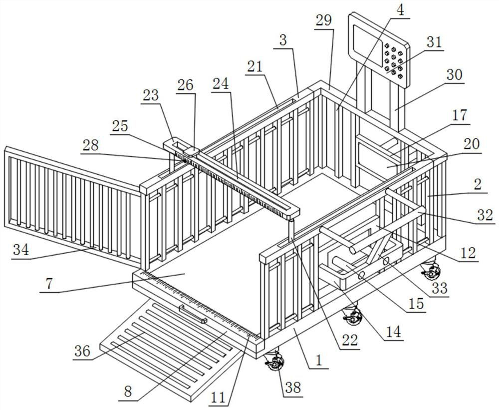
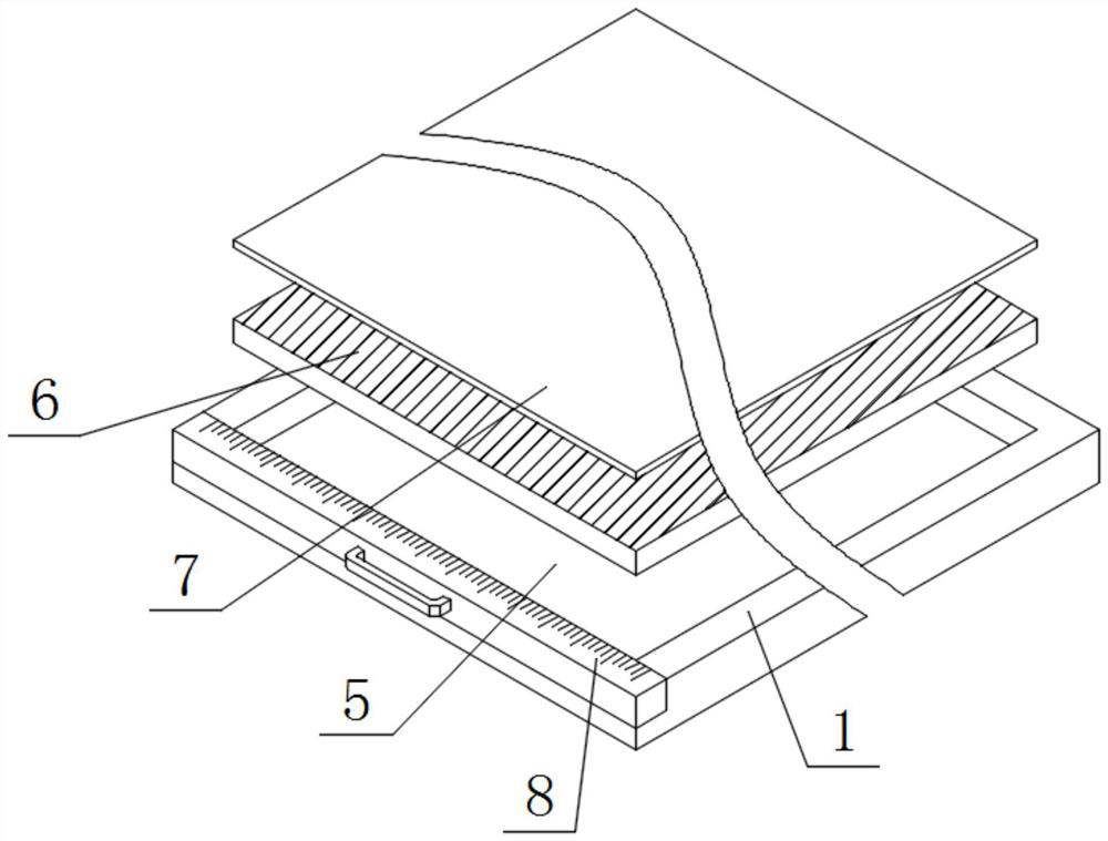
[0033] Such as figure 2 and image 3 As shown, a fully automatic body weight measuring device for sheep and its measuring system include a bottom plate 1, a grid plate 2, a composite bar 3 and a vertical bar 4, and two groups of grid plates 2 arranged front and back are installed on the top of the bottom plate 1 , the tops of the two groups of grid plates 2 are equipped with integrated rods 3, and the top of the bottom plate 1 is equipped with multiple sets of vertical rods 4 arranged in front and rear, and the vertical rods 4 are located on one side of the grid plates 2;
[0034] Specifically, the base plate 1 provides a suitable installation place for the components on its top, so that an enclosed frame can be formed between two groups of grid plates 2, multiple sets of vertical bars 4, movable door panels 34 and the base plate 1, so that The weight and body size of the sheep are measured inside the frame, and the sheep placed on the bottom plate 1 are prevented from jumpi...
Embodiment 2
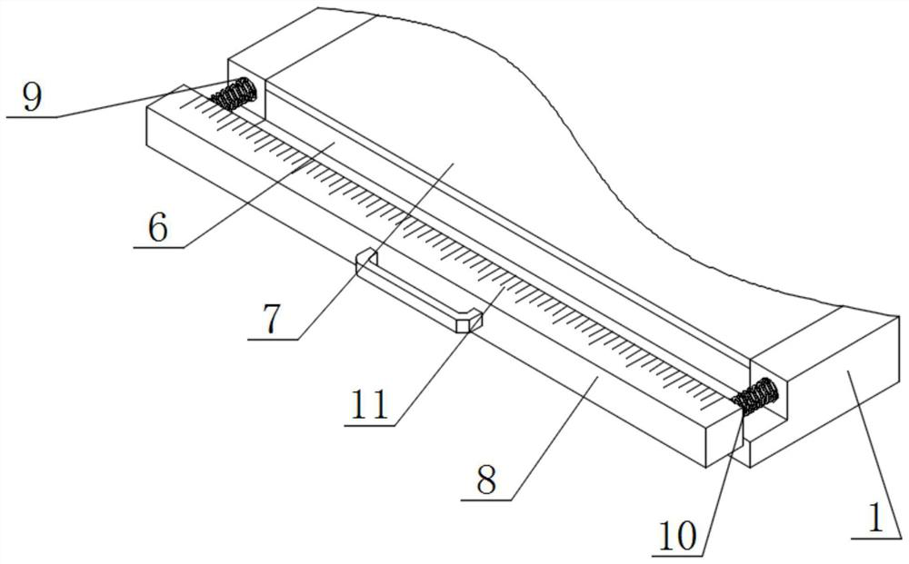
[0040] Such as figure 1 , Figure 4 and Figure 5 As shown, the top of the intercepting bar 8 is provided with a scale line 11, and the inner wall of one group of grid plates 2 is equipped with a fixed plate 12, and the front of the fixed plate 12 is provided with a through groove 13, and the front of the fixed plate 12 is equipped with a surrounding frame 14. Two groups of electric push rods 15 arranged side by side are installed on the front of the enclosure 14, and one end of the electric push rod 15 runs through the inside of the enclosure 14, and one end of the electric push rod 15 is equipped with a push plate 16, and the push plate one The outer wall of 16 is attached to the inner wall of through groove 13.
[0041] Specifically, the setting of the scale line 11 can allow the staff to intuitively understand the distance between the two groups of grid plates 2 before and after the device. At the same time, this size is included in the inside of the recorder 31 as the o...
Embodiment 3
[0045] Such as Figure 6 , Figure 6 and Figure 8 As shown, the tops of the two groups of integrated rods 3 are provided with moving grooves 21 , and telescopic sleeves 22 are installed on the bottom walls of the moving grooves 21 .
[0046] Specifically, the telescopic sleeve 22 can move inside the moving groove 21 under the drive of external force, so as to change the spatial position of the telescopic sleeve 22 and the parts above it. When it is necessary to enter the interior of the device, an upward thrust can be applied to the bearing plate 23 installed on the top of the telescopic sleeve 22, and then the telescopic sleeve 22 is urged to extend its own comprehensive length, thereby increasing the distance between the bottom of the bearing plate 23 and the top of the bottom plate 1. The space between the sheep and the sheep increases the space for the sheep to enter the interior of the device, reducing the sense of oppression that the carrying plate 23 brings to the sh...
PUM
 Abstract
Description
Claims
Application Information
 - R&D
- Intellectual Property
- Life Sciences
- Materials
- Tech Scout
- Unparalleled Data Quality
- Higher Quality Content
- 60% Fewer Hallucinations
Browse by: Latest US Patents, China's latest patents, Technical Efficacy Thesaurus, Application Domain, Technology Topic, Popular Technical Reports.
© 2025 PatSnap. All rights reserved.Legal|Privacy policy|Modern Slavery Act Transparency Statement|Sitemap|About US| Contact US: help@patsnap.com


