Insulation performance detection device for high-voltage motor
A high-voltage motor and insulation performance technology, applied in the direction of testing dielectric strength, etc., can solve the problems of being unable to isolate the external magnetic field and affecting the accuracy of test results
- Summary
- Abstract
- Description
- Claims
- Application Information
AI Technical Summary
Problems solved by technology
Method used
Image
Examples
Embodiment 1
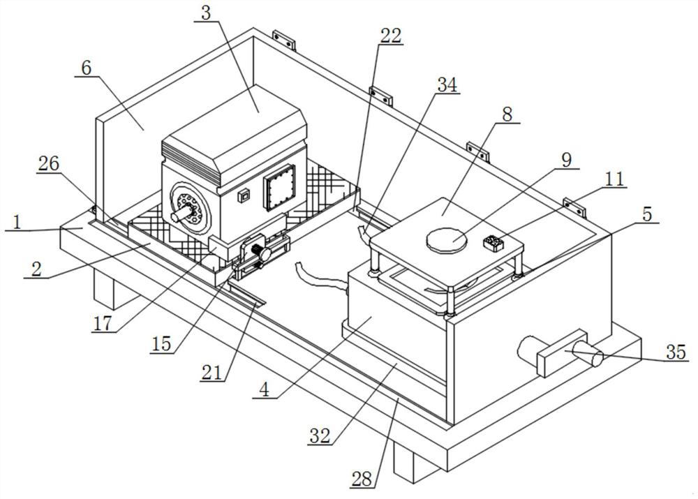
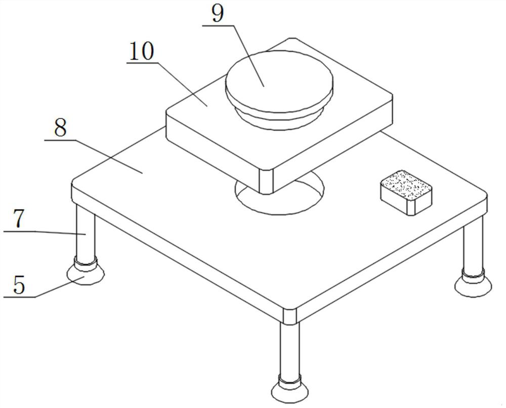
[0042] Such as figure 1 and figure 2 As shown, an insulation performance testing device for a high-voltage motor includes a bottom plate 1, a moving plate 2 for a high-voltage motor 3, a shaker 4, a rubber sucker 5 and a ferromagnetic enclosure 6, and a moving plate 2 is installed on the top of the bottom plate 1. A high-voltage motor 3 is installed on the top of the plate 2, and a shaker 4 is installed on the top of the bottom plate 1, and the shaker 4 is located on one side of the moving plate 2;
[0043] Specifically, the bottom plate 1 can provide a relatively stable place for the components on the top, and the moving plate 2 can provide a suitable place for the placement of the high-voltage motor 3, and a rubber pad is installed on the top, which increases the friction on the top of the moving plate 2. The high-voltage motor 3 is a motor with a rated voltage above 1000V, which has the advantages of large power and strong impact resistance. Most of the shaking meters 4 a...
Embodiment 2
[0049] Such as image 3 and Figure 4 As shown, the outer walls on both sides of the moving plate 2 are provided with adjustment grooves 12, and the outer walls on both sides of the moving plate 2 are equipped with supporting flaps 13 and limiting panels 14, and the bottom of the limiting panels 14 is connected to the bottom of the supporting flaps 13. The bottom is attached, and the bottom wall of the supporting folded plate 13 is equipped with an integrated board 15 , and the top of the integrated board 15 extends out of the inside of the limiting enclosure 14 .
[0050] A fastening screw 16 is installed through one side of the outer wall of the integrated plate 15 , and one end of the fastening screw 16 is installed with an expanded circular plate, and the outer wall of the expanded circular plate is attached to the inner wall of the adjustment groove 12 .
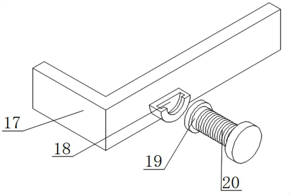
[0051] Two groups of L-shaped pressure plates 17 arranged diagonally are installed on the top of the moving plate 2,...
Embodiment 3
[0054] Such as Figure 5 and Figure 6 As shown, the top of the bottom plate 1 is provided with two sets of moving grooves 21 arranged front and back, and the bottom of the moving grooves 21 is equipped with two sets of fitting strips 22 arranged front and back, and the outer walls of the fitting strips 22 are attached to the inner walls of the moving grooves 21. , the bottom wall of the moving groove 21 is equipped with a fixed block 23, and the fixed block 23 is located on the side of the fitting bar 22 away from the rocker 4, and the top of the fixed block 23 is penetrated by a locking nail.
[0055] A notch 24 is provided on the side outer wall of the fitting bar 22 near the fixed block 23, a threaded sleeve 25 is installed on a side inner wall of the notch 24, and an electric push rod 26 is installed on the side outer wall of the fixed block 23 near the fitting bar 22, One end of the electric push rod 26 is installed with a threaded part 27 , and the outer wall of the th...
PUM
 Abstract
Description
Claims
Application Information
 - R&D
- Intellectual Property
- Life Sciences
- Materials
- Tech Scout
- Unparalleled Data Quality
- Higher Quality Content
- 60% Fewer Hallucinations
Browse by: Latest US Patents, China's latest patents, Technical Efficacy Thesaurus, Application Domain, Technology Topic, Popular Technical Reports.
© 2025 PatSnap. All rights reserved.Legal|Privacy policy|Modern Slavery Act Transparency Statement|Sitemap|About US| Contact US: help@patsnap.com


