
Multi-channel single-head unwinding equipment

A technology of unwinding equipment and unwinding racks, applied in the direction of winding strips, thin material handling, transportation and packaging, etc., can solve the problems of affecting efficiency, poor use effect, etc., to ensure stability, flexible adjustment and precision, The effect of improving unwinding efficiency and space utilization

Pending Publication Date: 2021-12-03
JI LONG MACHINERY CO LTD
View PDF6 Cites 3 Cited by
  • Summary
  • Abstract
  • Description
  • Claims
  • Application Information

AI Technical Summary

Problems solved by technology

[0002] The main function of the unwinding equipment is to pull the strip evenly from the material tray with a certain tension, usually including a rotating spindle, a magnetic powder brake and a deviation correction mechanism, so as to achieve a stable, uniform and controllable unwinding process of the strip , the current unwinding equipment is usually a single-lane and single-head unwinding structure. When there are many strips to be unrolled, multiple unwinding equipment needs to be used and placed in the factory space according to a certain layout to achieve In the process of multi-channel unwinding, when the related equipment moves, all of them need to be re-arranged at the same time, which greatly affects the efficiency and the use effect is poor, and it is difficult to meet the demand

Method used


Image

  • Multi-channel single-head unwinding equipment
  • Multi-channel single-head unwinding equipment
  • Multi-channel single-head unwinding equipment

Examples


Embodiment 1

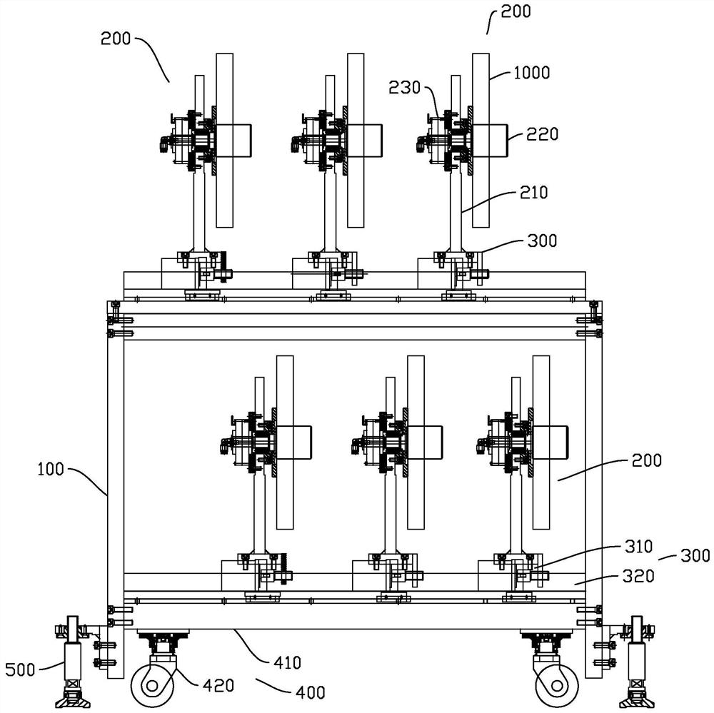
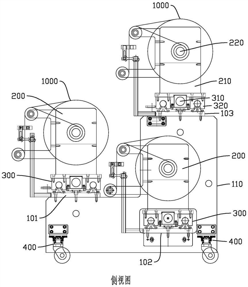
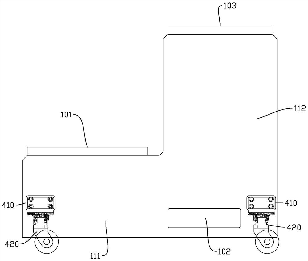
[0026] Such as Figure 1-2 In the structure shown, this multi-channel single-head unwinding equipment mainly includes a frame 100, an unwinding assembly 200 and a deviation correction assembly 300. The unwinding assembly is arranged on the frame to unwind the corresponding aluminum coils. And the deviation correction operation is performed on a single unwinding component through the deviation correcting component to ensure the stability of the unwinding process.

[0027] Specifically, the deviation correction assembly 300 includes a deviation correction driver 310 and a linear slide rail 320, the linear slide rail 320 is arranged on a placement frame, each of the deviation correction drivers 310 is connected to a single unwinding frame 210, and the deviation correction driver 310 Drive the connected unwinding rack 210 to move linearly along the linear slide rail 320, and the braking mechanism 230 includes a magnetic powder brake. The braking mechanism 230 is used to control th...


PUM


Abstract

The invention discloses a multi-channel single-head unwinding device which comprises a rack, a plurality of unwinding assemblies and a deviation rectifying assembly, placing frames are arranged on the rack, the placing frames are distributed in a staggered mode, each placing frame is provided with the multiple unwinding assemblies, and each unwinding assembly comprises an unwinding frame, an unwinding shaft and a brake mechanism. The brake mechanism is arranged on the unwinding frame, the unwinding shaft is connected with the brake mechanism, and a coiled material is arranged on the unwinding shaft; and the deviation rectifying assembly comprises deviation rectifying drivers and a linear sliding rail, the linear sliding rail is arranged on the placing frame, each deviation rectifying driver is connected with the corresponding unwinding frame, and the deviation rectifying drivers drive the unwinding frames connected with the deviation rectifying drivers to linearly move along the linear sliding rail. According to the multi-channel single-head unwinding device, multi-channel unwinding and independent control are achieved, the unwinding efficiency and the space utilization rate are improved, and adjustment is more flexible and accurate.

Description

technical field [0001] The invention relates to the technical field of unwinding mechanical equipment, in particular to an efficient and flexible multi-channel single-head unwinding equipment. Background technique [0002] The main function of the unwinding equipment is to pull the strip evenly from the material tray with a certain tension, usually including a rotating spindle, a magnetic powder brake and a deviation correction mechanism, so as to achieve a stable, uniform and controllable unwinding process of the strip , the current unwinding equipment is usually a single-lane and single-head unwinding structure. When there are many strips to be unrolled, multiple unwinding equipment needs to be used and placed in the factory space according to a certain layout to achieve In the process of multi-lane unwinding, when the relevant equipment moves, all of them need to be rearranged at the same time, which greatly affects the efficiency and the use effect is poor, and it is dif...

Claims


Application Information

Patent Timeline
IPC IPC(8): B65H16/02B65H16/04B65H16/10B65H23/032
CPCB65H16/021B65H16/04B65H16/103B65H23/032
Inventor 孟友彬廖界丰于远东
Owner JI LONG MACHINERY CO LTD
Learn More