Vehicle front lower protection cross beam, assembly and vehicle

A technology for vehicles and beams, applied in vehicle components, vehicle safety arrangements, bumpers, etc., can solve the problems of not being able to exert the strength of the protective beam body material, discounting the lightweight effect, and increasing the lower protective weight, so as to achieve local strengthening and lightweighting. Advantages, the effect of overcoming the complex protective structure, good promotion prospects and application value

Pending Publication Date: 2021-12-03
BAOSHAN IRON & STEEL CO LTD
View PDF3 Cites 0 Cited by
  • Summary
  • Abstract
  • Description
  • Claims
  • Application Information

AI Technical Summary

Problems solved by technology

The plane where the weld is located is parallel to the loading direction of the standard test, and the strength of the weld is lower than that of the base metal. Therefore, the weld will inevitably become the highest point of failure risk during the loading process, and the inherent strength of the material of the protective beam body cannot be exerted
The U-shaped fixed plate is used to locally reinforce the structure on the outside of the beam to make up for the impact of the strength drop at the weld, but this results in the application of additional materials, which increases the weight of the lower protection, and greatly reduces the lightweight effect
In addition, it needs to be connected by welding to form an integral beam, which puts forward higher precision requirements for pipe making and welding, which will inevitably increase the cost
[0007] Based on this, it is expected to obtain a new type of vehicle front lower protective beam with simple structure, local strengthening and light weight advantages, which can overcome many disadvantages such as complex structure, low strength and large mass of the existing commercial vehicle lower protective structure

Method used


Image

  • Vehicle front lower protection cross beam, assembly and vehicle
  • Vehicle front lower protection cross beam, assembly and vehicle
  • Vehicle front lower protection cross beam, assembly and vehicle

Examples


Embodiment Construction

[0039] The vehicle front lower protective crossbeam, assembly and vehicle described in the present invention will be further explained and illustrated in conjunction with specific embodiments and accompanying drawings. However, the explanations and illustrations do not constitute improper limitations on the technical solution of the present invention.

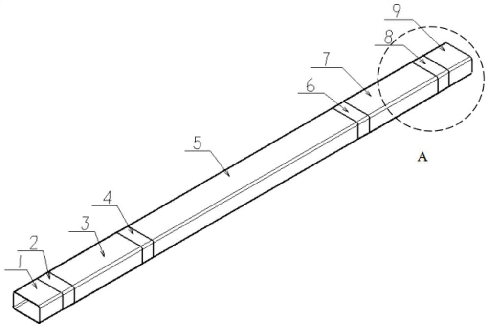
[0040] figure 1 It is a structural schematic diagram of an embodiment of the vehicle front lower protective beam according to the present invention.

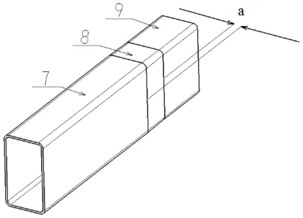
[0041] Such as figure 1As shown, in this embodiment, the vehicle front lower protective beam includes: middle section 5, reinforced transition section 4 and reinforced transition section 6, reinforced section 3 and reinforced section 7, distal transition section 2 and distal transition section 8 , distal segment 1 and distal segment 9. Wherein, the middle section is located in the middle of the longitudinal direction of the front lower protective beam of the vehicle, and the mi...


PUM


Abstract

The invention discloses a vehicle front lower protection cross beam which is provided with a middle section located in the middle in the length direction of the vehicle front lower protection cross beam, and a strengthening transition section, a strengthening section, a far-end transition section and a far-end section located at the end of the vehicle front lower protection cross beam are sequentially arranged from the middle section to the two ends respectively. The wall thickness of the strengthening section is larger than that of all other sections; the strengthening section, the middle section and the far-end section are each of an equal-thickness structure with the constant wall thickness in the length direction. The strengthening transition section and the far-end transition section are each of a variable-thickness structure, and the wall thickness of the variable-thickness structure changes continuously in the length direction. In addition, the invention further discloses a vehicle front lower protection cross beam assembly and a vehicle. The front lower protection cross beam of the vehicle has the advantages of being simple in structure, capable of being locally strengthened, obvious in light weight advantage and the like, light weight of the vehicle body is achieved under the condition that the safety performance requirement is met, and the front lower protection cross beam has good popularization prospects and application value.

Description

technical field [0001] The invention relates to an auto part, a component and a vehicle, in particular to a beam, a component and a vehicle. Background technique [0002] In the field of automobiles, considering the safety performance of the car, it is often necessary to install the front under protection on the vehicle. The front under protection of the vehicle is mainly used to prevent vehicles with small heights such as passenger cars from getting into N2 and N3 categories in the event of a traffic accident. In commercial vehicles with large heights such as trucks, it can avoid serious accidents and improve the collision safety of vehicles. [0003] Domestic "GB26511-2011 Commercial Vehicle Front Lower Protection Requirements" has put forward clear mandatory requirements for the installation of commercial vehicle front lower protection. However, due to considerations of fuel economy and environmental protection, vehicle lightweight has become one of the main goals pursue...

Claims


Application Information

Patent Timeline
Patent Type & Authority Applications(China)
IPC IPC(8): B60R19/18
CPCB60R19/18B60R2019/1806B60R19/02
Inventor 郭运石磊袁静玺顾浩肖华吴彦骏
Owner BAOSHAN IRON & STEEL CO LTD
Why Eureka
Try Eureka