
Manipulator

Inactive Publication Date: 2021-12-03
ZHEJIANG OCEAN UNIV
View PDF0 Cites 0 Cited by
  • Summary
  • Abstract
  • Description
  • Claims
  • Application Information

AI Technical Summary

Problems solved by technology

It can replace people to carry out heavy labor to realize the mechanization and automation of production. It is widely used in machinery manufacturing, light industry and atomic energy and other departments. In the process of using the existing manipulator, due to the limitation of the installation site It is necessary to adjust the height according to different transfer places in order to increase the transfer height. The usual adjustment method is to increase the height of the installation base to achieve the goal, but using this method requires multiple debugging during the adjustment process, which increases the use of At the same time, in the process of installing the structure in the manipulator, the traditional method usually uses bolts to fix it. This fixing method is not conducive to the later disassembly, thereby reducing the maintenance efficiency.

Method used


Image

  • Manipulator
  • Manipulator
  • Manipulator

Examples


Embodiment Construction

[0022] The following will clearly and completely describe the technical solutions in the embodiments of the present invention with reference to the accompanying drawings in the embodiments of the present invention. Obviously, the described embodiments are only some, not all, embodiments of the present invention. Based on the embodiments of the present invention, all other embodiments obtained by persons of ordinary skill in the art without making creative efforts belong to the protection scope of the present invention.

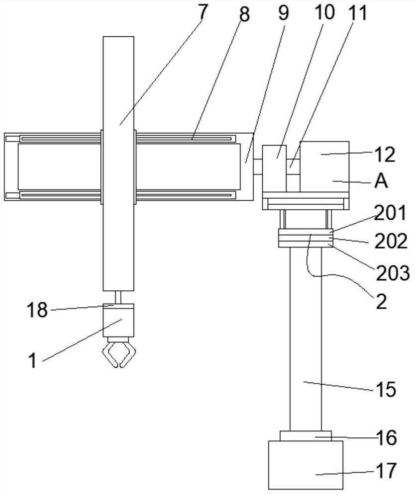
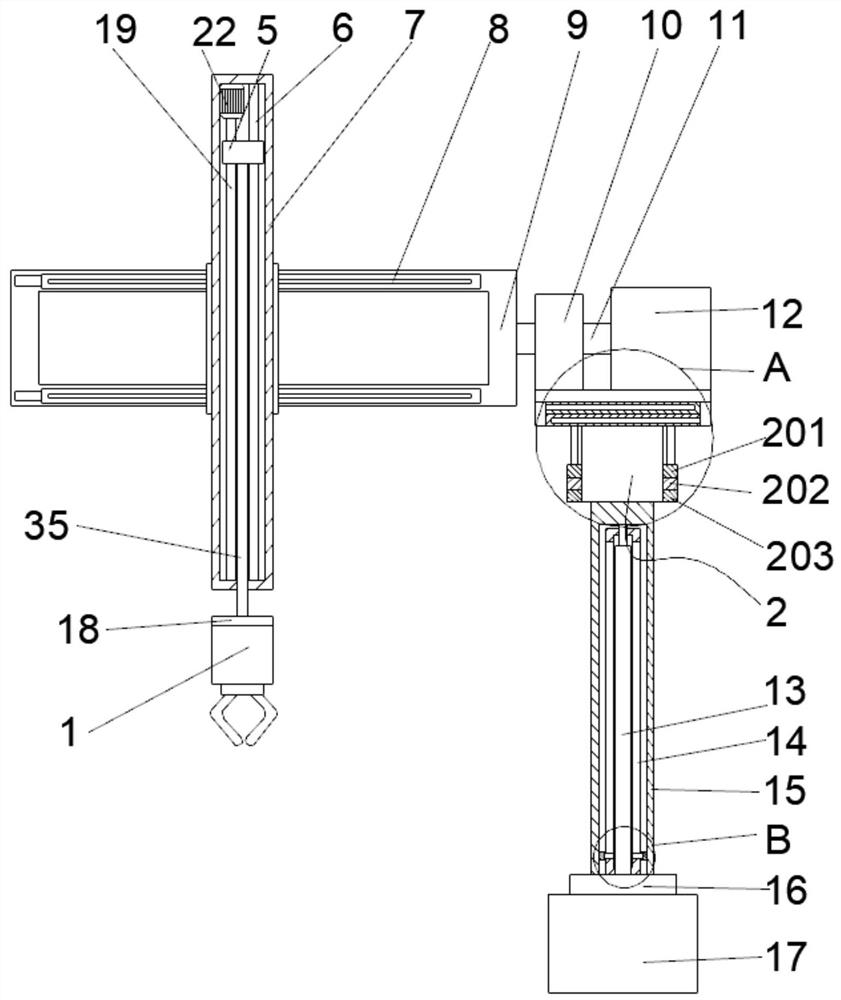
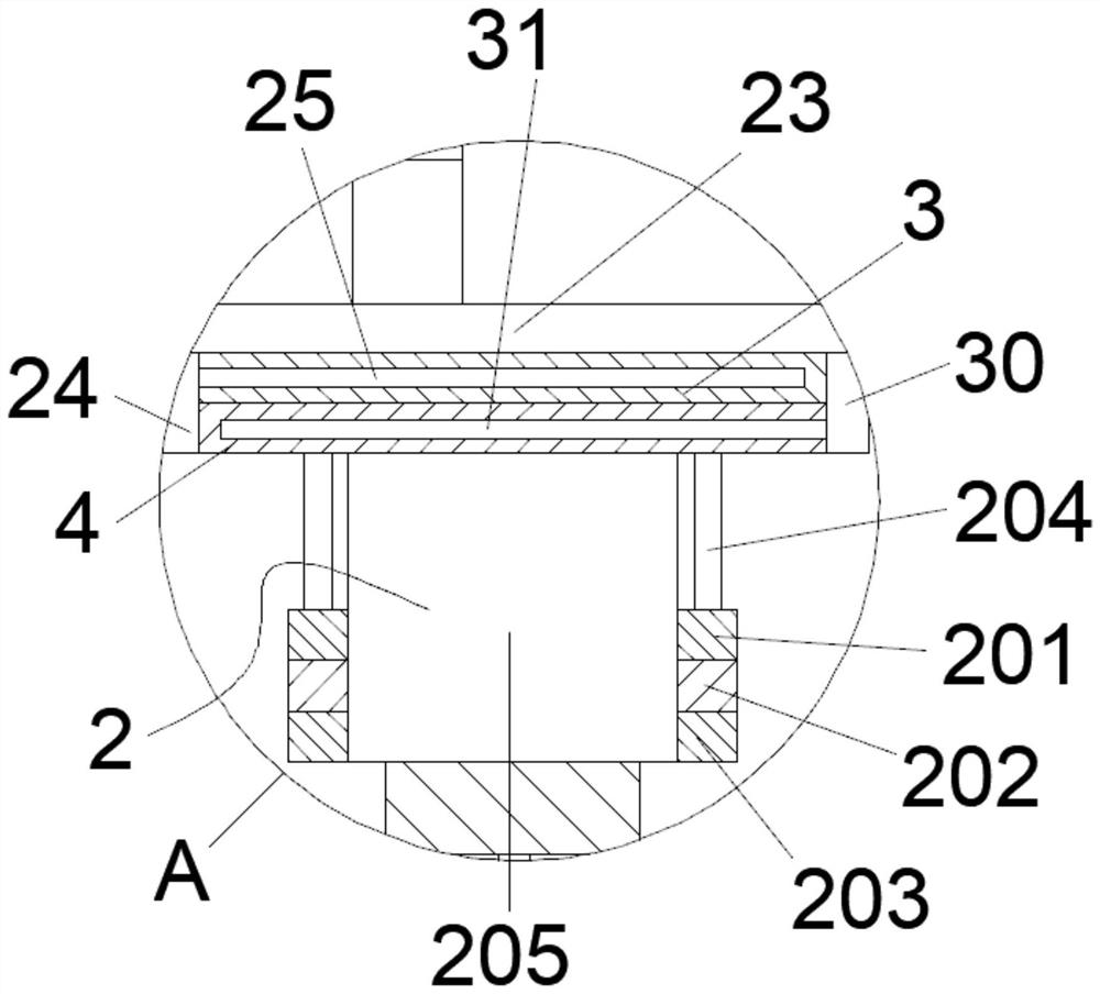
[0023] see Figure 1-7 , the present invention provides a technical solution: a manipulator, including a manipulator main body 1, a fixed assembly 2, a fixed plate 3, a first limit plate 4, a slider 5, a limit rod 6, an installation box 7, and a cylinder slide rail 8 , mounting frame 9, fixed seat 10, rotating shaft 11, rotating cylinder 12, lifting cylinder 13, limit pipe 14, moving pipe 15, first connecting block 16, rotating base 17, second connecting block...


PUM


Abstract

The invention discloses a manipulator. The manipulator comprises a manipulator body, a fixing assembly, a fixing plate, a first limiting plate, a sliding block, a limiting rod, a mounting box, an air cylinder sliding rail, a mounting frame, a fixing seat, a rotating shaft, a rotating air cylinder, a lifting air cylinder, a limiting pipe, a moving pipe, a lead screw, a lifting motor, a first mounting plate, a first barrier strip, a first limiting column, a second mounting plate, a second barrier strip, a second limiting plate, a second limiting column, a third barrier strip, a third limiting column, a fourth barrier strip, a fourth limiting column, a third limiting plate and a fixing column. According to the manipulator, through the mounted lifting air cylinder, the distance between the bottom end of the manipulator body and the bottom end of a rotating base can be conveniently adjusted, the manipulator can be used in different scenes, and the difficulty degree during mounting is reduced; through the arranged fixing assembly, the fixing plate and the first limiting plate are mutually fixed, the second limiting plate and the third limiting plate are mutually fixed, a traditional mounting mode is changed, dismounting is facilitated, and the maintenance efficiency is improved.

Description

technical field [0001] The invention relates to the technical field of manipulators, in particular to a manipulator. Background technique [0002] Manipulator refers to an automatic operating device that can imitate certain actions and functions of the human hand and arm to grab, carry objects or operate tools according to a fixed program. It is mainly composed of three parts: the actuator, the drive mechanism and the control system. It can replace people to carry out heavy labor to realize the mechanization and automation of production. It is widely used in machinery manufacturing, light industry and atomic energy and other departments. In the process of using the existing manipulator, due to the limitation of the installation site It is necessary to adjust the height according to different transfer places in order to increase the transfer height. The usual adjustment method is to increase the height of the installation base to achieve the goal, but using this method requir...

Claims


Application Information

Patent Timeline
Patent Type & Authority Applications(China)
IPC IPC(8): B25J9/12B25J9/14B25J19/00
CPCB25J9/123B25J9/144B25J9/146B25J19/00
Inventor 周崇浩朱从容
Owner ZHEJIANG OCEAN UNIV
Learn More