Electrode plate and wearable defibrillation device

A technology of electrode plates and covers, applied in electrodes, mechanical equipment, cardiac defibrillators, etc., can solve problems such as low reliability, gas leakage, defibrillation equipment not working in time, etc., and achieve improved safety and timely protection Effect

Pending Publication Date: 2021-12-03
MICROPORT SORIN CRMSHANGHAICO LTD
View PDF0 Cites 0 Cited by
  • Summary
  • Abstract
  • Description
  • Claims
  • Application Information

AI Technical Summary

Problems solved by technology

But the shortcoming of this scheme is that in order to make the gas can squeeze out the capsule, the gas-generating drug is used to explode to generate a sufficient air pressure. At this time, the box that accommodates the capsule can only be designed according to the maximum strength, so that the box must be thick enough and hard enough to make the capsule The patient is uncomfortable when wearing it, and the willingness to wear it is not high
Not only that, but the safety of gas-promoting medicine is difficult to guarantee, and in the case of multiple capsules, if the strength of the capsules is inconsistent, individual capsules will not be able to be opened, because the capsule that ruptures first will cause gas leakage, which will quickly reduce the gas pressure, making the Other capsules cannot be opened to release the conductive paste, and the discharge of the conductive paste is difficult to ensure, so that the defibrillation equipment cannot work in time, and the patient cannot be rescued in time, so the reliability is not high

Method used


Image

  • Electrode plate and wearable defibrillation device
  • Electrode plate and wearable defibrillation device
  • Electrode plate and wearable defibrillation device

Examples


Embodiment 1

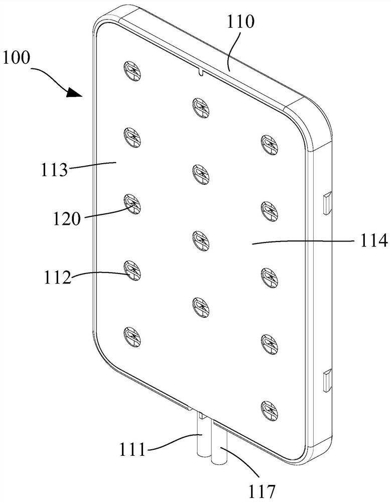
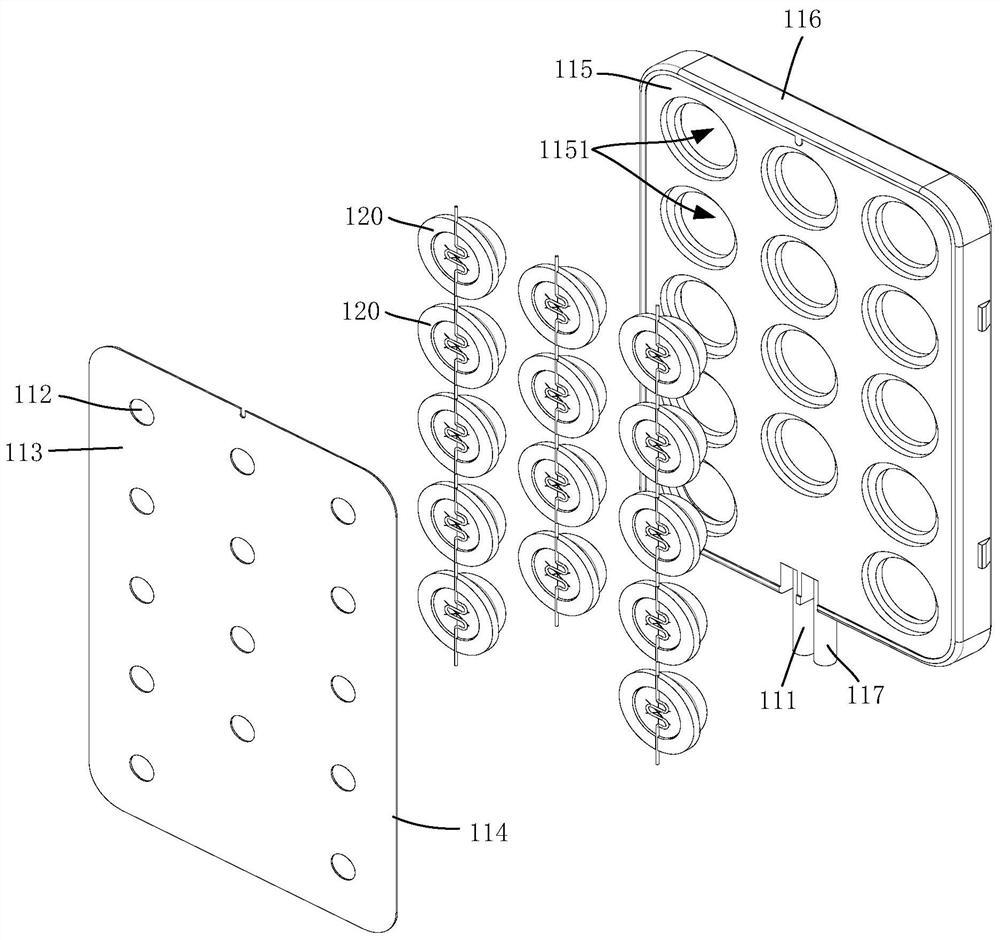
[0066] figure 2 with image 3 They are respectively a schematic diagram of the assembled structure and a schematic diagram of the disassembled structure of the electrode plate provided by the preferred embodiment 1 of the present invention. Such as figure 2 with image 3 As shown, this embodiment provides an electrode plate 100 for cardiac defibrillation. The electrode plate 100 specifically includes a sealed casing 110 and a capsule 120; the capsule 120 is arranged in the sealed casing 110 and is used to store conductive paste .

[0067] Figure 4 with Figure 5 They are respectively the front view of the capsule provided by the preferred embodiment 1 of the present invention and the Figure 4 A cross-section along line A-A of the capsule shown. Such as Figure 4 ~ Figure 5 As shown, the capsule 120 includes a body 121 having a hollow cavity 122 in which the conductive paste is stored. The cavity 122 is provided with an outlet 123; the outlet 123 has an open state ...

Embodiment 2

[0081] After further research, the inventor found that under the same defibrillation area, the more capsules loaded on the electrode plate, the smaller the space available for the electrode plate to load the conductive paste. Therefore, in fact, more capsules cannot be used to load more conductive paste. Specifically, in Embodiment 1, for example, the electrode plate 100 is loaded with 14 capsules 120, there will be gaps between the 14 capsules 120, no matter how large the gaps are, these gaps are completely unusable, relatively speaking, the more gaps , the smaller the area available for loading the conductive paste on the sealed case, this reduces the total loading of the conductive paste. If the thickness of the electrode plate is increased in order to increase the loading capacity of the conductive paste, the cost will be increased, especially the electrode plate will be thicker, making it uncomfortable for the patient to wear. Not only that, the more capsules there are, ...


PUM


Abstract

The invention relates to an electrode plate and a wearable defibrillation device. The electrode plate comprises a sealing shell and capsules arranged in the sealing shell; the sealing shell is provided with an inflation port and glue overflow ports; the glue overflow ports are formed in an exposed surface of the sealing shell and the exposed surface has conductivity; the capsule comprises a body and a cover, the body is provided with a hollow cavity and an outlet communicating with the cavity, and the cavity is used for storing a conductive paste, and isolated from an empty cavity of the sealing shell; the cover is arranged at an outlet and used for sealing the outlet; and a gap formed after the cover is broken communicates with the outlet and the glue overflow port, such that the conductive paste in the cavity flows out to the exposed surface through the outlet, the gap of the cover and the glue overflow port in sequence. The device has advantages of automatically coating the conductive paste, protecting a patient in time, and improving release safety of the conductive paste.

Description

technical field [0001] The invention relates to the technical field of medical devices, in particular to an electrode plate and a wearable defibrillation device. Background technique [0002] Ventricular fibrillation is a relatively common heart disease in life. It has the characteristics of no aura of onset, short rescue time (only 4 minutes from onset to death), and high sudden death rate. For such patients, the current rescue method mainly uses high DC voltage to defibrillate the heart by discharging it, so that the heart returns to a normal rhythm. There are four main types of defibrillation equipment: [0003] (1) The mobile defibrillator can be moved, but it is bulky and inconvenient to carry. Therefore, it is mostly used in hospitals; [0004] (2) Automatic defibrillator (AED), which is easy to carry and placed in a conspicuous position in public places; [0005] (3) Implantable defibrillator (ICD), which can be operated fully automatically and can be implanted int...

Claims


Application Information

Patent Timeline
IPC IPC(8): A61N1/39A61N1/04B05C11/10B05C11/11F16J15/10
CPCA61N1/3904A61N1/3968A61N1/046A61N1/0484F16J15/10B05C11/10B05C11/11A61B5/361A61B5/256A61B5/4836A61B2560/0406A61B2562/04A61B5/6805A61B5/6843
Inventor 何明晨
Owner MICROPORT SORIN CRMSHANGHAICO LTD
Why Eureka
Try Eureka