Synoptophore

A synoptic and near-infrared technology, applied in the field of synoptics, can solve the problems of time-consuming doctors, long time period, difficult real-time monitoring of the detection process, etc., and achieve the effect of convenient record keeping, automatic operation and rich content.

Pending Publication Date: 2021-12-03
上海青研科技有限公司
View PDF0 Cites 1 Cited by
  • Summary
  • Abstract
  • Description
  • Claims
  • Application Information

AI Technical Summary

Problems solved by technology

Because the structure of the traditional synoptic machine is relatively complicated, it is not easy for young patients to learn the above operation steps
[0006] (2) The training content is relatively simple and less interesting
However, visual training takes a long period of time, and the training objects are often young children. This will lead to children who use traditional synoptic machines for visual training to feel that the training is boring, and they are unwilling to cooperate subjectively, which will affect the training effect. Negative Effects
[0007] (3) It is inconvenient to adjust the position of the lens barrel
Because the interpupillary distance of different people is different, the traditional synoptic machine needs to manually adjust the position of the lens barrel, and it is difficult to completely make the interpupillary distance of the synopic machine exactly equal to the real interpupillary distance of the subject only by subjective judgment.
[0008] (4) The detection process is difficult to monitor in real time
In the process of using the traditional synoptic machine, it is difficult to monitor and judge in real time whether the subject's eyes are staring at the visual mark or the corresponding picture according to the doctor's requirements
[0009] (5) Data is not easy to save
The traditional synopic machine has a mechanical structure, and the inspection and training data need to be observed with the naked eye and recorded manually, which consumes the doctor's time, and the results recorded manually are not easy to save and find

Method used


Image

  • Synoptophore
  • Synoptophore
  • Synoptophore

Examples


Embodiment Construction

[0050] Below in conjunction with specific embodiment, further illustrate the present invention. It should be understood that these examples are only used to illustrate the present invention and are not intended to limit the scope of the present invention. In addition, it should be understood that after reading the teachings of the present invention, those skilled in the art can make various changes or modifications to the present invention, and these equivalent forms also fall within the scope defined by the appended claims of the present application.

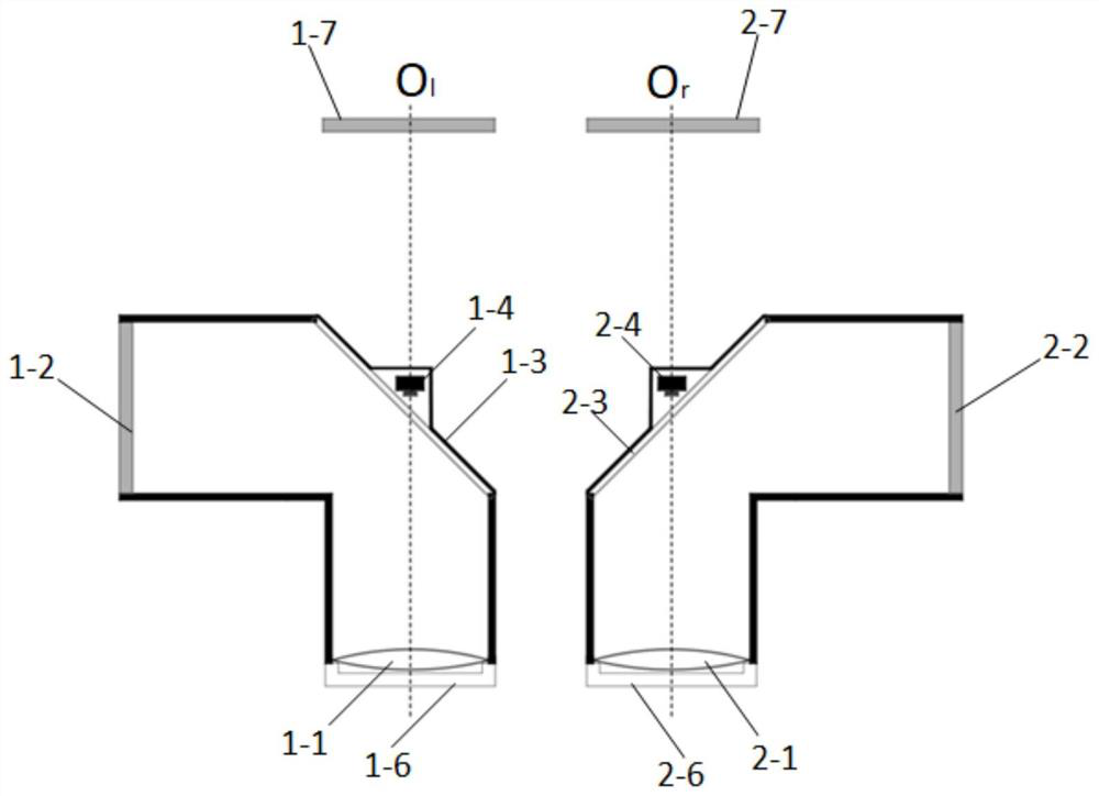
[0051] A synoptic machine disclosed in this embodiment includes a left optical module 1; a right optical module 2; a chin rest; and a calculation and control module. FIG. 1( a ) is a structural schematic diagram of a top view of the left optical module and the right optical module.

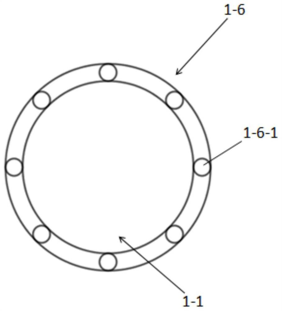
[0052] Wherein, the left optical module 1 includes a left eyepiece 1-1, a left display screen 1-2, a left plane lens 1-3, a left near-infrared ca...


PUM


Abstract

The invention provides a synoptophore. The synoptophore is characterized in that the synoptophore comprises a left optical module, a right optical module, a lower jaw support and a calculation and control module, wherein the left optical module can move left and right and can move up and down relative to a position of the lower jaw support; relative positions of the left optical module and the lower jaw support can be adjusted, so that a left eyepiece can be aligned with the center of a left eye pupil of a detected person; the right optical module can move left and right and can move up and down relative to the position of the lower jaw support; and relative positions of the right optical module and the lower jaw support can be adjusted, so that a right eyepiece can be aligned with the center of a right eye pupil of the detected person. The synoptophore has the beneficial effects that operation is automatic, and use is convenient; examination and training contents are rich, diversified and interesting, so that a child patient is willing to use the synoptophore cooperatively; relative positions of the eyepieces and eyes can be automatically adjusted; in an examination process, an eye watching position of the detected person can be monitored in real time, and rotation of eyeballs can be automatically tracked; and examination and training data can be conveniently recorded and stored.

Description

technical field [0001] The invention relates to an ophthalmic medical device, in particular to a synoptic machine for binocular vision inspection and training. Background technique [0002] The synopic machine is a commonly used instrument for binocular vision function inspection and binocular vision training. The traditional synoptic machine includes a left lens barrel and a right lens barrel, which can rotate around the X-axis, Y-axis, and Z-axis through a mechanical movement mechanism respectively. Among them, the pitching movement of the lens barrel around the X axis corresponds to the upward and downward rotation of the eyeball; the movement of the lens barrel around the Y axis corresponds to the internal rotation and external rotation of the eyeball; the movement of the lens barrel around the Z axis corresponds to the level of the eyeball direction of movement. [0003] The traditional synoptic machine also contains replaceable pictures, which are inserted at the end...

Claims


Application Information

Patent Timeline
IPC IPC(8): A61B3/00A61B3/028A61B3/032A61B3/08A61B3/113A61B3/15A61H5/00
CPCA61B3/0041A61B3/0075A61B3/0083A61B3/0091A61B3/154A61B3/152A61B3/113A61B3/08A61B3/085A61B3/0285A61B3/032A61B3/0025A61H5/00A61H5/005A61H2201/5007
Inventor 杜煜詹培忠
Owner 上海青研科技有限公司
Why Eureka
Try Eureka