Motor controller integrated assembly for electric vehicle and electric vehicle with motor controller integrated assembly
A motor controller and controller technology, applied in the field of electric vehicles, can solve problems such as hidden dangers of service life of wire components, electromagnetic interference, and hidden dangers of liquid leakage
- Summary
- Abstract
- Description
- Claims
- Application Information
AI Technical Summary
Problems solved by technology
Method used
Image
Examples
Embodiment 1
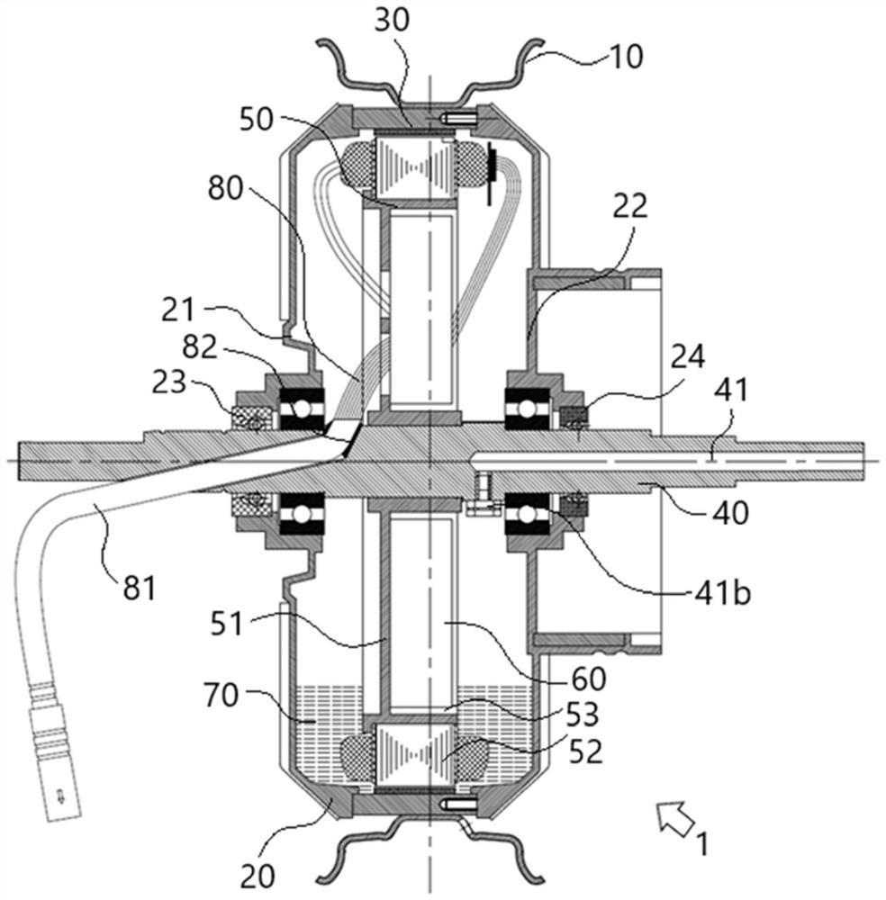
[0029] Example 1: see figure 1 As shown, a motor controller integrated assembly 1 for an electric vehicle, the motor specifically adopts a brushless permanent magnet synchronous motor; it includes a permanent magnet rotor assembly 30 installed integrally with the electric wheel hub 10 and the motor housing 20, and is located in the permanent magnet The inner circumference of the rotor assembly 30 and the stator assembly 50 installed integrally with the motor shaft 40, the stator assembly 50 is located inside the motor housing 20, wherein the end surface of the stator assembly 50 is installed with a controller 60 for driving and controlling the motor, Preferably, in this embodiment, the stator assembly 50 includes a stator core 52 installed on the outer periphery of the stator holder 51, the stator holder 51 is installed integrally with the motor shaft 40, and one end of the stator holder 51 is provided on the motor shaft. The mounting groove 53 on the periphery of 40, the cont...
Embodiment 2
[0036] Embodiment 2: On the basis of the above embodiment 1, please refer to image 3 and combine figure 1 As shown, the preferred solution of the motor shaft 40 is further proposed in Embodiment 2. The motor shaft 40 and the stator assembly 50 are installed as a whole, and the stator assembly 50 is located inside the motor housing 20, wherein the motor shaft 40 is respectively provided with The wire harness penetration passage 42 and the air passage 41, both the wire harness penetration passage 42 and the air passage 41 extend from the outside of the motor housing 20 to the inside of the motor housing 20, wherein the wire harness penetration passage 42 and the air passage 41 are not connected; preferably Specifically, in this embodiment, the wire harness penetration channel 42 and the air channel 41 are respectively located at both ends of the stator assembly 50, ensuring that there will be no interference between the two;
[0037] Preferably, in this embodiment, the air pas...
Embodiment 3
[0041] Embodiment 3: for the remaining technical solutions and embodiments of this embodiment 3, please refer to Figure 5 and Figure 6 As shown, this embodiment 3 further proposes another implementation of the motor shaft 40'. In this embodiment 3, the air passage 41' adopts a bent shape. Specifically, preferably, the air valve 41b and the air passage 41' adopt In the vertical installation structure, the air channel port 41c' located outside the motor housing 20 is located at the non-end portion of the motor shaft 40'.
PUM
 Abstract
Description
Claims
Application Information
 - R&D
- Intellectual Property
- Life Sciences
- Materials
- Tech Scout
- Unparalleled Data Quality
- Higher Quality Content
- 60% Fewer Hallucinations
Browse by: Latest US Patents, China's latest patents, Technical Efficacy Thesaurus, Application Domain, Technology Topic, Popular Technical Reports.
© 2025 PatSnap. All rights reserved.Legal|Privacy policy|Modern Slavery Act Transparency Statement|Sitemap|About US| Contact US: help@patsnap.com


