
Conveying line stretching and redirection method

A conveying line and conveying device technology, which is applied to conveyors, conveyor objects, conveyor control devices, etc., can solve the problem of unfavorable information identification and in-out operation efficiency, low bin sorting and conveying operation efficiency, and high use cost. problems, to improve the efficiency of information identification and storage and outbound operations, improve the efficiency and availability of sorting operations, and simplify the control device and process.

Pending Publication Date: 2021-11-30
QINGDAO KENGIC AUTOMATION EQUIP CO LTD
View PDF8 Cites 0 Cited by
  • Summary
  • Abstract
  • Description
  • Claims
  • Application Information

AI Technical Summary

Problems solved by technology

[0005] The disadvantages of the above-mentioned prior art are as follows: First, there is a lack of fast and accurate online reorientation solutions, and the material box conveying and reorientation are performed step by step, and extra execution equipment is added too much, which makes the on-site space occupation larger and the use cost higher. Second, the existing technology is difficult to adapt to the application scenarios of all box-type conveyor lines, and the versatility is poor. It is necessary to configure special reversing or redirection equipment for specific conveying operations; third, the efficiency of bin sorting and conveying operations Low, the accuracy of reversing and redirecting is low, which is not conducive to improving the efficiency of information identification and warehousing operations, and the control device and process are complicated, which may easily cause the failure of sorting tasks

Method used


Image

  • Conveying line stretching and redirection method
  • Conveying line stretching and redirection method
  • Conveying line stretching and redirection method

Examples


Embodiment 1

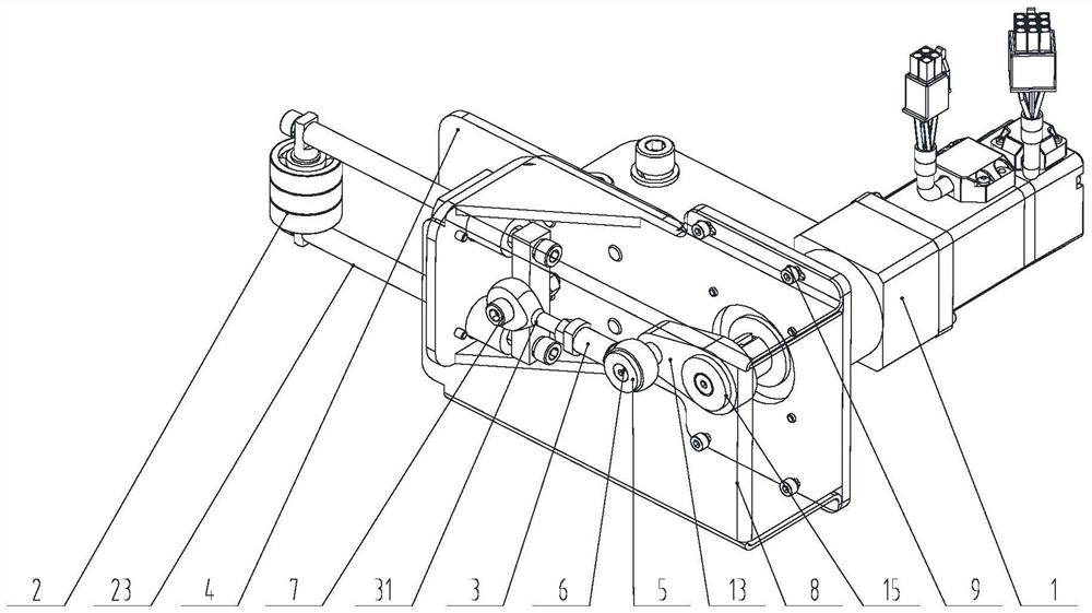
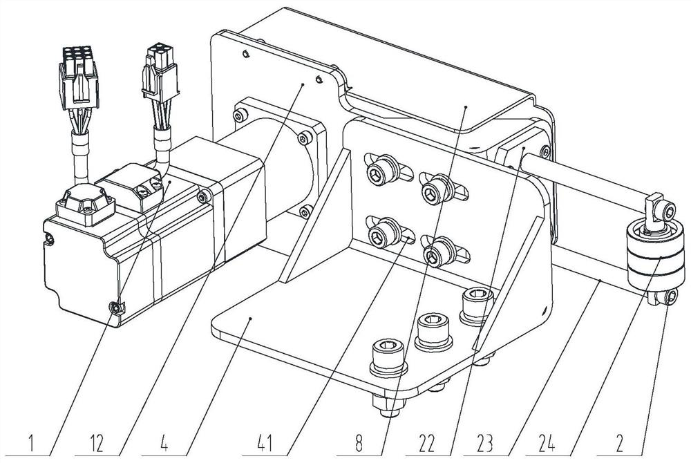
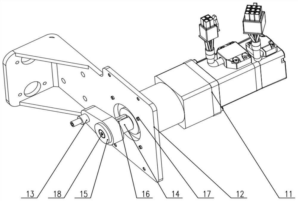
[0038] Example 1, as shown in Figures 1 Figure 8 As shown, the conveying line telescoping modire device 100 of the conveying line telescoping process according to the present application is applied to the horizontal flip to implement the tank 400 during the delivery process to achieve an online 90 ° reform operation.

[0039] The conveying line telescoping modire device 100 is integrally mounted on the side portion of the conveying device, in the present embodiment, the conveying device is a slant roller 200, or may be another type of delivery device such as a belt conveyor.

[0040] As shown in FIG. 1, the conveying line telescoping modire device 100 includes a body connection modifier 4 attached to the side portion of the skemper roller 200 side, and a driving traction that is connected to the body connection adjustment board 4, respectively. The assembly 1 and the telescopic sliding assembly 2 are connected between the drive traction assembly 1 and the telescopic sliding assemb...


PUM


Abstract

The invention relates to a conveying line stretching and redirection method. A telescopic redirection crank sliding rod device is independently arranged at one side of a conveying line, a material box is horizontally turned over through continuous abutting and jacking of an end bearing, and finally 90-degree redirection in the conveying process is completed. A conveying line telescopic redirection device is arranged on the side portion of a conveying device, a visual recognition device detects and judges that the material box enters the conveying device in the direction of the short edge or the long edge of the material box, and whether online 90-degree redirection operation is conducted on the material box or not is determined; under the driving of a servo motor speed reducer, a rotating crank rotates circumferentially with a shaft connection point of an output shaft of the servo motor speed reducer as the circle center, and the rod end bearing is pushed and pulled in a reciprocating mode in the longitudinal direction through a bearing connection assembly; and the extending rod end bearing continuously abuts against and jacks the material box, and the material box is horizontally turned over in the conveying process to complete 90-degree redirection.

Description

Technical field [0001] The present invention relates to a bin-type cargo to achieve a scalable relevance control method of 90 ° flip during delivery, belonging to the field of logistics sorting. Background technique [0002] With the rapid development of e-commerce, express and warehousing industry, various automatic sorting and delivery equipment have been generally adopted in the cargo sorting work site to replace manual operation, thereby significantly improvement of the speed and efficiency of sorting operations. [0003] On the conveying line of the existing box, it is usually required to convey in the set direction, such as the long side of the tank to remain parallel to the conveying line (ie, the short side of the required tank is perpendicular to the delivery line), so that Scanning and information identification of the tank outer packaging bar code, and adapting to the needs of specific devices (such as shuttle car box storage, etc.). When the tank conveying direction c...

Claims


Application Information

Patent Timeline
IPC IPC(8): B65G47/248B65G43/08
CPCB65G47/248B65G43/08B65G2203/04B65G2201/0258
Inventor 龙进军于付龙李帅邱吉知田伟
Owner QINGDAO KENGIC AUTOMATION EQUIP CO LTD
Learn More