
Intelligent steel bar bender for machining lower side cabinet hinge

A steel bar bending and intelligent technology, applied in the field of intelligent steel bar bending machine, can solve the problems of uncontrollable angle, unsuitable for the production of lower side door hinges, etc., to meet the requirements of processing accuracy and assembly requirements, and ensure the effect of regular shape

Pending Publication Date: 2021-11-30
重庆阳天人防工程设备有限公司
View PDF7 Cites 4 Cited by
  • Summary
  • Abstract
  • Description
  • Claims
  • Application Information

AI Technical Summary

Problems solved by technology

[0005] Although the above-mentioned patent is provided with a replaceable positioning block, the actual bending angle cannot be controlled, and the corresponding inner diameter cannot be bent according to different types of steel bars, so it is not suitable for the production of lower side door hinges

Method used


Image

  • Intelligent steel bar bender for machining lower side cabinet hinge
  • Intelligent steel bar bender for machining lower side cabinet hinge
  • Intelligent steel bar bender for machining lower side cabinet hinge

Examples


Embodiment 1

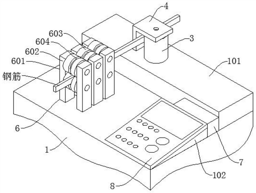
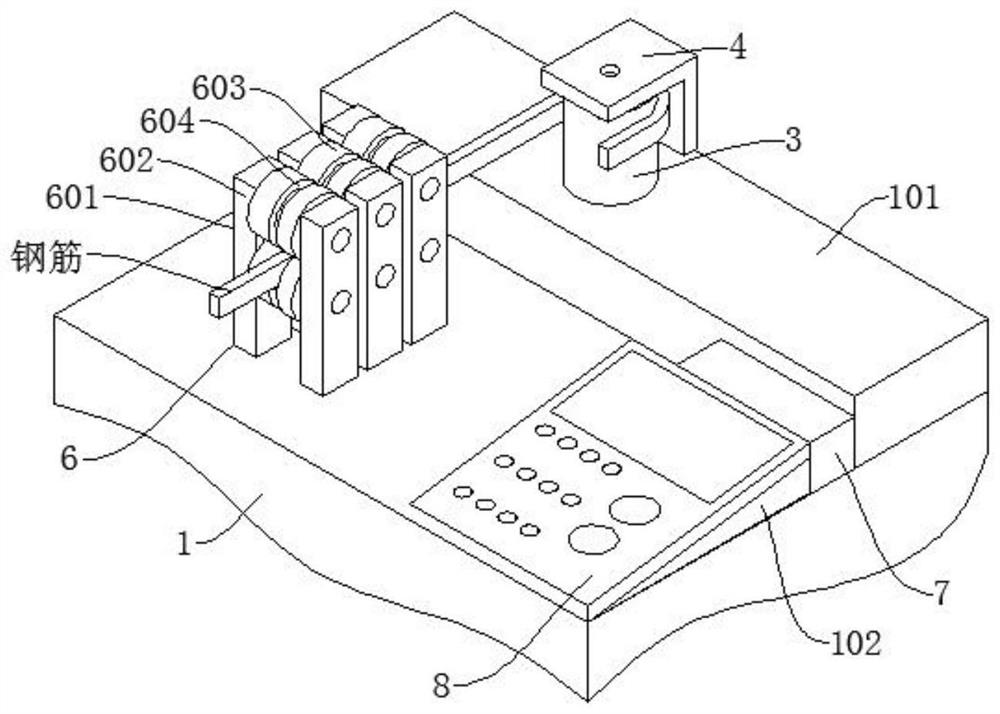
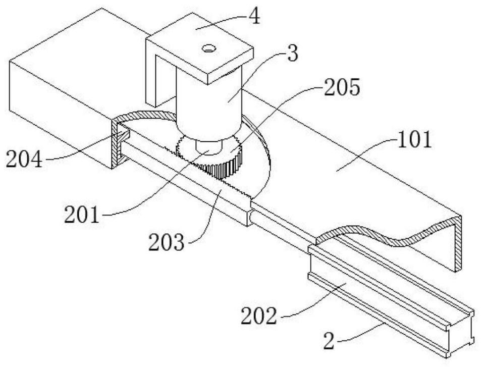
[0031] Such as figure 1 and figure 2 As shown, an intelligent steel bar bending machine for processing lower side door hinges includes a steel bar bending machine body 1, a support box 101 is installed at the front side edge of the upper surface of the steel bar bending machine body 1, and a support box 101 is installed in the support box 101. A bending drive mechanism 2 is installed, and a relief hole is penetrated above the support box 101. The drive shaft 201 of the bending drive mechanism 2 is inserted into the lower end of the bending shaft 3 through the relief hole, and the bending drive mechanism 2 is driven by The shaft 201 drives the bending shaft 3 to rotate positively and negatively. The upper end of the bending shaft 3 is installed with a limit plate 4 through a positioning nail 5. The limit plate 4 is an L-shaped structural plate. The vertical side plate of the limit plate 4 602 faces to the left, a curved feed inlet is formed between the vertical side plate 602...

specific Embodiment 1

[0049] Assuming that the steel bar type has been determined, replace the bending shaft, transmission gear, and transmission rack of the corresponding size. If the radius r of the bending shaft is 5cm, the central angle of the bending angle is 60°. According to the above structure and calculation method, it can be obtained:

[0050]

[0051] Then L=5.23, which means that the moving length of the pressure cylinder pulling the rack is 5.23cm.

[0052] Verify that the above specific embodiment 1 is: the bending axis radius r is 5cm, then the circumference C=2πr, which is 31.4cm, and the calculation formula of the central angle of the bending angle is:

[0053]

[0054] Then n=60°.


PUM


Abstract

The invention discloses an intelligent steel bar bender for machining a lower side cabinet hinge. The intelligent steel bar bender comprises a steel bar bender body, wherein a support box is mounted on the edge of the front side of the upper surface of the steel bar bender body; a bending driving mechanism is mounted in the support box; a receding hole is formed in the upper part of the support box in a penetrating manner; a driving shaft of the bending driving mechanism penetrates through the receding hole to be inserted into the lower end of a bending shaft; a limiting plate is mounted at the upper end of the bending shaft through a positioning nail, and the vertical side plate surface of the limiting plate faces leftwards; a steel bar straightening mechanism is arranged on the upper surface of the steel bar bender body; a discharging hole of the steel bar straightening mechanism leads to a bending feeding hole; and a control box and a control panel are further arranged on the upper surface of the steel bar bender body and both mounted at the right side of the steel bar straightening mechanism. The specific length of a transmission rack pulled by a pressure cylinder to move is calculated in the mode that the pressure cylinder drives a gear and the rack to do reciprocating motion, so that accurate calculation and bending operation of the central angle of the steel bar bending angle are achieved, and intelligent steel bar bending is achieved.

Description

technical field [0001] The invention belongs to the technical field of steel bar bending equipment, in particular for bending steel bars for lower side door hinges, and in particular to an intelligent steel bar bending machine for processing lower side door hinges. Background technique [0002] General gondola wagons are the main type of railway wagons in my country, accounting for about 60% of all railway wagons in my country. The side wall of the universal gondola compartment is provided with twelve lower door frames altogether, and a lower door is fixedly installed in each lower door frame. This design is for convenient unloading of bulk goods such as gravel and coal. [0003] The lower side door hinge seat is located on the top of the lower side door panel, and is the hinge shaft connecting the lower side door hinges. There is a horizontal channel steel welded on the inner wall of the cargo gondola on the upper side of several lower side doors. The lower side door hinge ...

Claims


Application Information

Patent Timeline
Patent Type & Authority Applications(China)
IPC IPC(8): B21F1/02B21F1/00
CPCB21F1/02B21F1/004
Inventor 陈界
Owner 重庆阳天人防工程设备有限公司
Learn More