
Test tube cleaning equipment for blood department

A technology for cleaning equipment and departments, applied in the field of test tube cleaning equipment, can solve problems such as low cleaning efficiency and incomplete test tubes, and achieve the effects of improved cleaning efficiency, convenient handling, and accelerated drying efficiency

Pending Publication Date: 2021-11-30
雷小兰
View PDF13 Cites 1 Cited by
  • Summary
  • Abstract
  • Description
  • Claims
  • Application Information

AI Technical Summary

Problems solved by technology

[0004] In order to overcome the shortcomings of incomplete manual cleaning of test tubes and low cleaning efficiency, the technical problem is to provide a test tube cleaning equipment for blood departments with thorough cleaning and high cleaning efficiency

Method used


Image

  • Test tube cleaning equipment for blood department
  • Test tube cleaning equipment for blood department
  • Test tube cleaning equipment for blood department

Examples


Embodiment 1

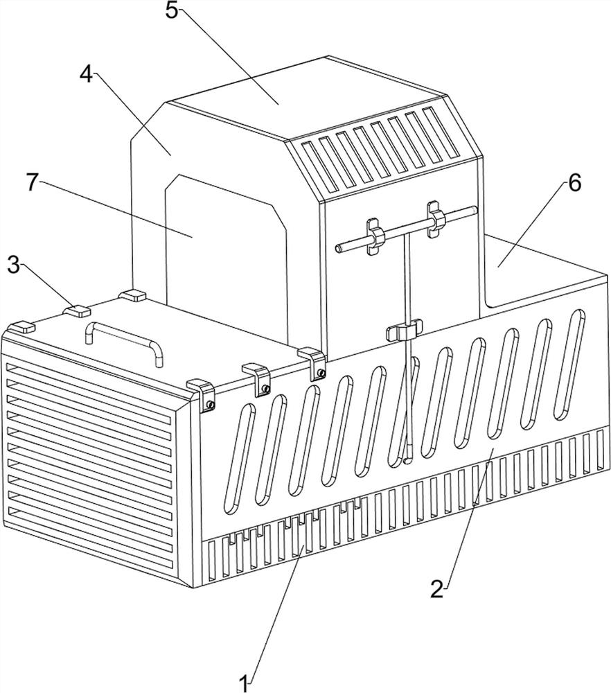
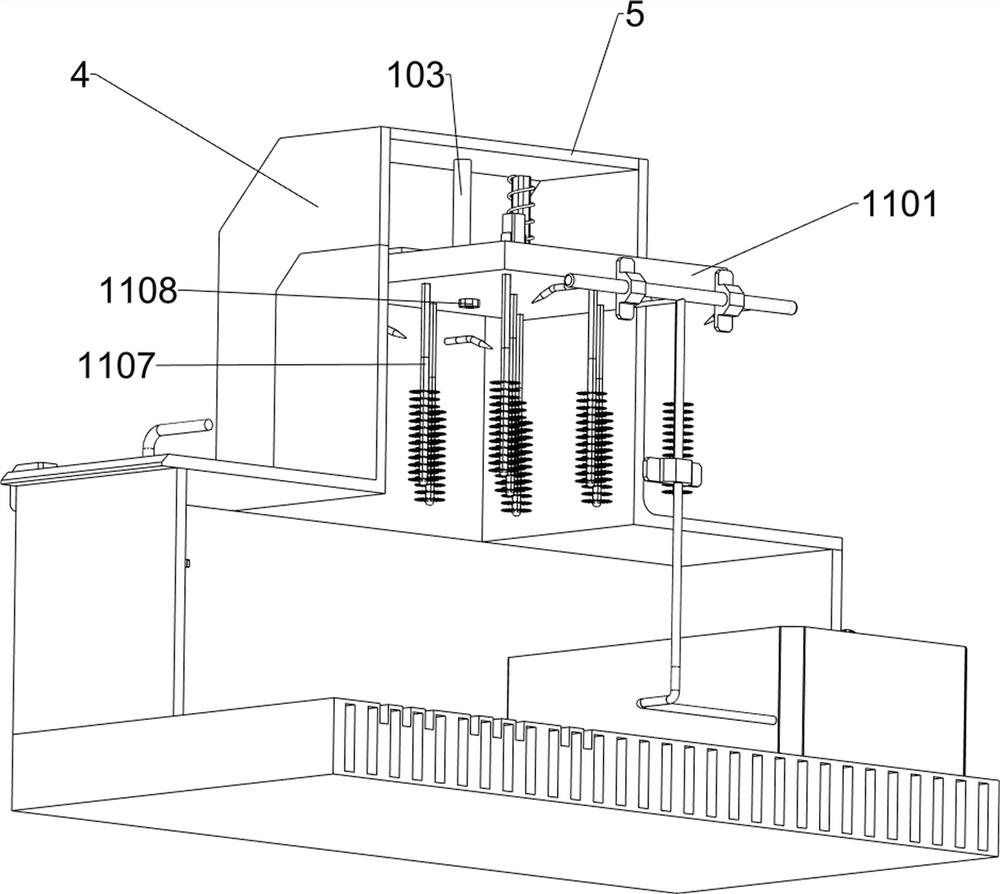
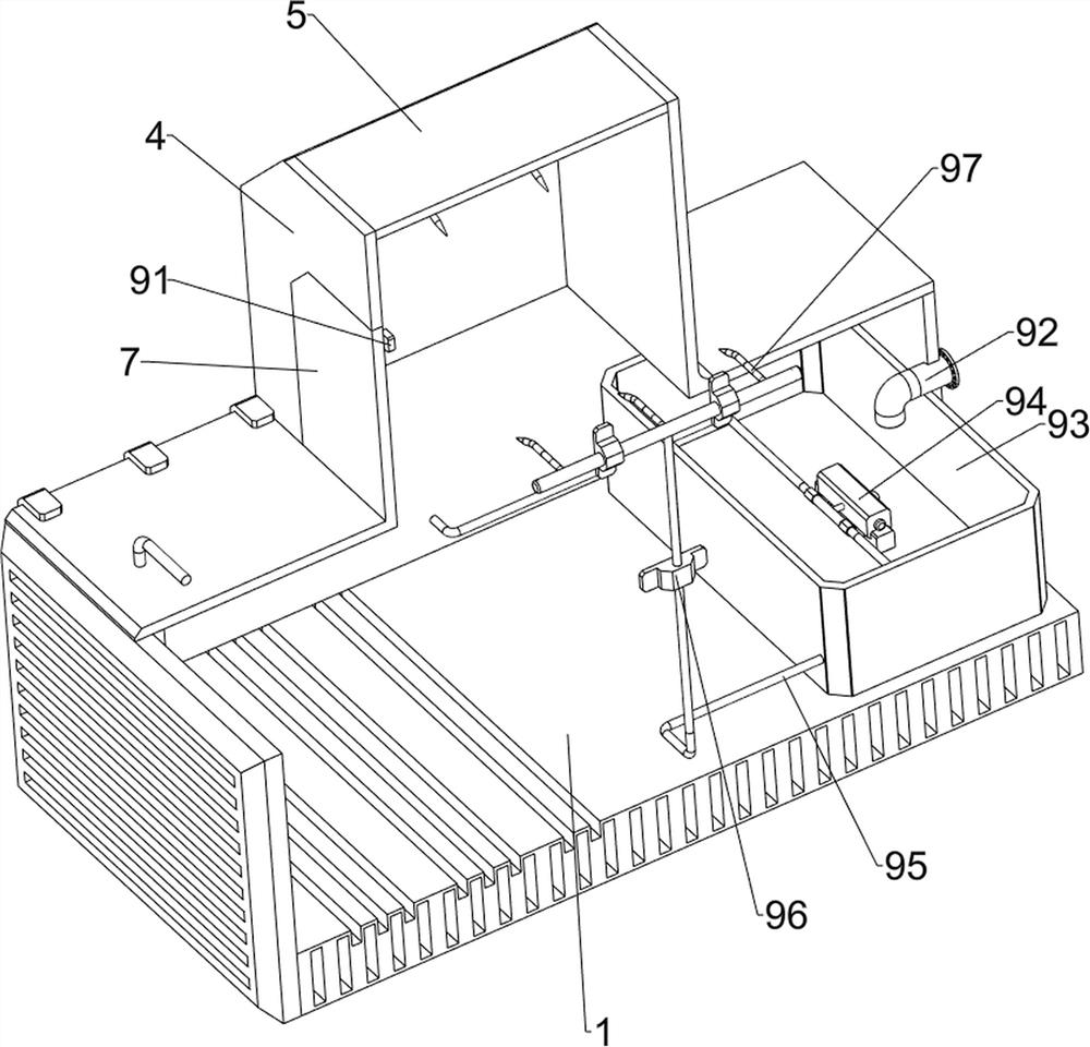
[0031] A kind of test tube cleaning equipment for blood department, such as Figure 1-5 As shown, it includes a base plate 1, a coaming plate 2, a limit buckle 3, a front baffle 4, a frame 5, a rear baffle 6, a pull plate 7, a water spray mechanism 9, a telescopic mechanism 10 and a cleaning mechanism 11, and the base plate 1 There is a shroud 2 inside, and three limit buckles 3 are arranged symmetrically front and rear on the upper left side of the shroud 2, a rear baffle 6 is arranged on the right side of the top of the shroud 2, a front baffle 4 is arranged on the left side of the top of the shroud 2, and the front A frame 5 is provided between the baffle 4 and the rear baffle 6, the bottom of the frame 5 is connected in the middle of the top of the enclosure 2, and a pull plate 7 is placed slidingly on the left side of the top of the enclosure 2, and the pull plate 7 is in contact with the limit buckle 3 , Water spray mechanism 9 is provided between base plate 1 and coamin...

Embodiment 2

[0037] On the basis of Example 1, such as image 3 , Figure 6 , Figure 7 and Figure 8 As shown, a moving mechanism 12 is also included, and the moving mechanism 12 includes a third mounting block 1201, a second electric push rod 1202, a guide groove 1203, a rack 1204 and a second distance sensor 1205, and the front and rear of the right side of the enclosure 2 The third mounting block 1201 is symmetrically arranged on both sides, and the second electric push rod 1202 is arranged between the third mounting block 1201 on the same lateral side. The left and right sides of the enclosure 2 are symmetrically provided with a guide groove 1203, and the guide groove The right side of 1203 is provided with a rack 1204, and the top of the left side of the second electric push rod 1202 on the rear side is provided with a second distance sensor 1205.

[0038] Also includes a fixed mechanism 13, the fixed mechanism 13 includes a connecting frame 1301, a fixed snap ring 1302, a rotatin...


PUM


Abstract

The invention relates to test tube cleaning equipment, in particular to test tube cleaning equipment for a blood department. The technical problem is to provide the test tube cleaning equipment for the blood department, which is thorough in cleaning and relatively high in cleaning efficiency. According to the technical scheme, the test tube cleaning equipment for the blood department comprises a bottom plate, a surrounding plate, limiting buckles, a front baffle, a frame, a rear baffle, a pulling plate, a water spraying mechanism, a telescopic mechanism and a cleaning mechanism; the surrounding plate is arranged on the bottom plate; three limiting buckles are symmetrically arranged on the surrounding plate; the rear baffle is arranged on one side of the surrounding plate; the front baffle is arranged on one side of the surrounding plate; the frame is arranged between the front baffle and the rear baffle and connected with the surrounding plate; and the pulling plate is slidably placed on one side of the surrounding plate. Through cooperation of the cleaning mechanism, the telescopic mechanism and the water spraying mechanism, the equipment can automatically clean test tubes without the need of manual cleaning, and the cleaning efficiency is improved.

Description

technical field [0001] The invention relates to a test tube cleaning device, in particular to a test tube cleaning device for blood departments. Background technique [0002] Test tubes are a type of medical equipment. They are usually used to hold various medicines, blood and other liquids. Because test tubes are reused, test tubes that do not meet hygienic requirements are prone to cross-infection when they are used for the second time. Where they are used The finished test tubes require extremely rigorous cleaning. However, the existing test tubes are generally cleaned manually, and only one can be cleaned manually at a time. After the cleaning is completed, it needs to be dried and sterilized, which causes a lot of labor for the medical staff, and the test tubes cleaned by this method are often Can not meet the requirements of re-use, if re-use is easy to cross-infection. [0003] Therefore, it is necessary to develop a test tube cleaning device for blood departments t...

Claims


Application Information

Patent Timeline
IPC IPC(8): B08B9/28B08B9/34B08B9/36B08B13/00F26B21/00
CPCB08B9/0808B08B9/0813B08B9/28B08B9/34B08B9/36B08B13/00F26B21/004
Inventor 雷小兰
Owner 雷小兰
Learn More