A large-scale wing component flip-up hanging device

A hanging device and component technology, which is applied in the field of large-scale wing parts turning over hanging device, can solve the problems of out-of-control impact force of the wing, achieve uniform force, good shock absorption effect, and reduce damage

Active Publication Date: 2022-01-25
CHENGDU AIRCRAFT INDUSTRY GROUP
View PDF10 Cites 0 Cited by
  • Summary
  • Abstract
  • Description
  • Claims
  • Application Information

AI Technical Summary

Problems solved by technology

[0005] The invention aims to solve the problem of out-of-control and excessive impact force in the process of turning over the wings in the prior art, and proposes a large-scale wing part turning and hanging device, which can not only The drop of the wing acts as a buffer to reduce structural damage, and it can also monitor the force of the rope in real time, so that the operator can better understand the force of the wing during hoisting

Method used


Image

  • A large-scale wing component flip-up hanging device
  • A large-scale wing component flip-up hanging device
  • A large-scale wing component flip-up hanging device

Examples


Embodiment 1

[0043] This embodiment is the most basic implementation.

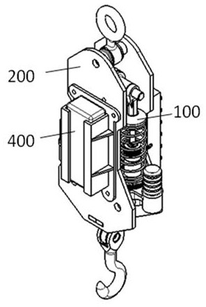
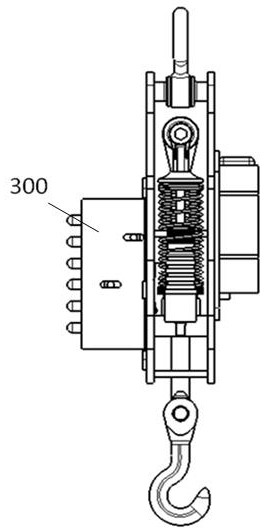
[0044] This embodiment discloses a large-scale wing component turning over hanging device, such as Figure 1-2 As shown, it includes four parts: a buffer hook mechanism 100 , a support frame 200 , an indicator light device 300 , and a power supply box 400 . Among them, the buffer hook mechanism 100 and the support frame 200 are used as the main functional structure for hanging products and playing a buffering role. The indicator light device 300 is used to display the working state of the hook 150 . The buffer hook mechanism 100 is installed in the support frame 200 , the power supply box 400 and the indicator light device 300 are respectively installed on both sides of the support frame 200 , and the power supply box 400 is used to supply power to the indicator light device 300 .

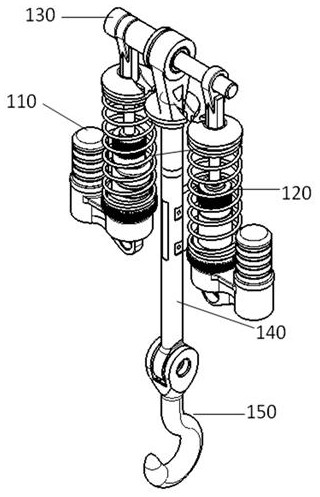
[0045] Such as image 3 As shown, the buffer hook mechanism 100 includes a threaded pin 130 , a shock absorber 110 , a transmission rod 1...

Embodiment 2

[0050] On the basis of Embodiment 1, further, the control component 160 is a vertical strip structure, and a strip-shaped hole is opened on the side wall of the transmission rod 140, and one side of the control component 160 is snapped into the transmission rod. The elongated hole of 140 is fixed inside, and the other side of the control part 160 exceeds the side surface of the transmission rod 140, and the side surface is provided with a boss 161, and the edge of the boss 161 transitions smoothly with the end face of the control part 160.

[0051] Such as Figure 7 As shown, the support frame 200 includes a suspension ring 210, a left support 220, and a right support 230. The left support 220 and the right support 230 are fixedly connected to form a rigid box structure. Such as Figure 8-9 As shown, the guide plate includes an upper guide plate 240 and a lower guide plate 250 arranged in parallel between the left support member 220 and the right support member 230, and the c...


PUM


Abstract

The invention discloses a large-scale wing component flip-up hanging device, which belongs to the technical field of hoisting and includes a support frame, a buffer hook mechanism and an indicator light device; the buffer hook mechanism includes a threaded pin rod, a shock absorber, a transmission pull rod and a hook; The upper end of the transmission rod is socketed on the threaded pin through the bearing, and its lower end is fixedly connected with the hook; the shock absorber is symmetrically arranged on both sides of the transmission rod; the support frame is provided with a guide plate, and the guide plate is provided for limiting the transmission rod. A guide hole that reciprocates in the vertical direction, the transmission rod passes through the guide hole and is in clearance fit with the guide hole; a control part is arranged on the transmission rod, and the control part is used to follow the movement of the transmission rod to control the state of the indicator light device Variety. The invention can buffer the falling of the wing during the turning over of the wing, reduce the damage of the structure, and monitor the force situation of the rope in real time, so that the operator can make a correct judgment.

Description

technical field [0001] The invention relates to a hanging device, in particular to a hanging device for turning over a large wing part. Background technique [0002] During the assembly process of aircraft wing components, it is often necessary to turn over the wing (the upper and lower wing surfaces are turned over). The existing wing turning scheme is: connect the intersection hole of the wing through a sling, and turn the bottom against the bracket. In the process of turning over, the rope should not be pulled too tight due to the suspension and the rope during the wing turning process. If the rope is too tight, the wing will be pulled to move horizontally, which will cause relative movement between the wing and the bracket, or even fall. out of the bracket. In order to prevent the wing from moving horizontally with the rope, it is necessary to loosen the rope when the wing is in a state perpendicular to the ground, so that the wing can perform flipping motion around the...

Claims


Application Information

Patent Timeline
Patent Type & Authority Patents(China)
IPC IPC(8): B66C1/14B66C13/08B66C13/18B66C13/16F16F15/02
Inventor 刘良存高文翔郑筱舟张立新张进海王佳鑫卢大伟陈晓龙周欣康许博
Owner CHENGDU AIRCRAFT INDUSTRY GROUP
Why Eureka
Try Eureka